

Carburetor diagram «Ozone»
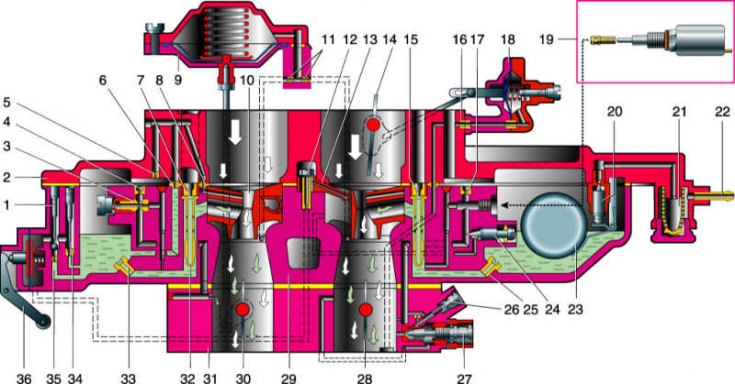
1 - screw for adjusting the stroke of the inlet valve of the accelerator pump; 2 - carburetor cover; 3 - fuel jet of the transition system of the second chamber; 4 - air jet of the transition system; 5 – econostat air jet; 6 – econostat fuel jet; 7 - the main air jet of the second chamber; 8 - emulsion jet econostat; 9 - pneumatic actuator of the throttle valve of the second chamber; 10 - small diffuser; 11 - jets; 12 - delivery valve of the accelerating pump; 13 - accelerator pump sprayer; 14 - air damper; 15 - the main air jet of the first chamber; 16 - jet starting device; 17 - idle air jet; 18 - automatic starting device; 19 - solenoid valve with idle fuel jet; 20 - needle valve for fuel supply; 21 - fuel filter; 22 - fuel supply fitting; 23 - float; 24 - screw for factory adjustment of the idle system; 25 - the main fuel jet of the first chamber; 26 - adjusting screw for the quality of the working mixture; 27 - adjusting screw of the composition of the working mixture; 28 - throttle valve of the first chamber; 29 - body of the float chamber; 30 - throttle valve of the second chamber; 31 - throttle body; 32 - emulsion tube; 33 - main fuel jet of the second chamber; 34 - bypass valve of the accelerator pump; 35 - inlet valve of the accelerator pump; 36 - accelerator pump drive lever.
Design Description
A carburetor is currently being installed on a VAZ-2106 car «Ozone» model DAAZ 2107-1107010-20. On a VAZ-21065 car, a DAAZ 21053-1107010 carburetor is used (model based on the carburetor family «Solex»).
Carburetor «Ozone» - emulsion type, two-chamber, with a falling flow. It has one balanced float chamber, two main dosing systems, an enrichment device (econostat) in the second chamber, an autonomous idle system, transitional systems of the first and second chambers, a diaphragm accelerator pump with a spray in the first chamber, an idle system electromagnetic shut-off valve, a spool device for removing crankcase gases into the throttle space, a pneumatic throttle actuator of the second chamber. The control of the air damper of the first chamber is manual, with a cable drive. After starting the engine, the damper is automatically opened by a diaphragm-type starting device under the action of a vacuum in the intake piping. The carburetor is equipped with a vacuum outlet to control the ignition timing controller.
Fuel is supplied to the carburetor through a strainer and needle valve. The valve is mechanically connected to the float and maintains a certain level of fuel in the float chamber.
From the float chamber, fuel enters through the main fuel jets (first and second chambers) into emulsion wells and emulsion tubes, where it mixes with air entering through the main air jets. The air-fuel emulsion enters through the atomizers into the small and large diffusers of the carburetor.
The fuel channel of the idle system is blocked by an electromagnetic shut-off valve after the ignition is turned off. The normal state of the energized valve is open.
The idle system draws fuel from the emulsion well of the first chamber. The fuel passes through the idle jet, structurally integrated with the electromagnetic shut-off valve, and mixes with air entering through the idle air jet and the openings of the transition system of the first chamber. The resulting emulsion through two channels (one has a calibrated hole - a jet, and the other has an adjusting screw, otherwise called a quality screw) is supplied to the hole blocked by the needle of the quantity screw, where it is additionally mixed with air and then enters the inlet pipeline through the emulsion hole. The composition of the mixture is regulated by the quality screw.
Partial throttle opening (before switching on the main dosing system) the air-fuel mixture enters the chambers through vias - two in each chamber.
The econostat provides fuel supply directly from the float chamber to the econostat atomizer, which is located in the diffuser of the second chamber. The econostat is switched on at maximum power modes, further enriching the working mixture.
Accelerator pump - diaphragm type, mechanically driven from the axis of the throttle valve of the first chamber. With a sharp opening of the damper, a portion of fuel is injected through the sprayer into the first chamber of the carburetor, enriching the mixture. The pump is equipped with ball valves. One valve - a check valve - is located in the channel connecting the float chamber with the cavity of the accelerator pump. It opens when the pump cavity is filled with fuel and closes when fuel is injected by the diaphragm. Another valve is located in the atomizer. It opens under the pressure of the injected fuel and closes under the weight of the ball as soon as the fuel supply stops. Excess fuel during injection flows through the bypass jet back into the float chamber.
The performance of the pump depends on the profile of the cam, the diameter of the hole in the bypass jet, the profile and length of the adjusting needle in the channel of the bypass jet. The accelerator pump is not subject to adjustment during operation.
The starter consists of the choke, choke lever, telescopic link, throttle link, diaphragm mechanism and throttle control actuator. When pulling the drive handle («suction») from the driver's seat, the air damper closes, and the throttle valve of the first chamber opens slightly by 0.7–0.8 mm (starting clearance). At the first flashes in the cylinders, the vacuum behind the throttle valve is transmitted to the diaphragm, which opens the air damper through the rod and rod. The maximum opening of the damper is adjusted by the diaphragm stop screw located under the plug screw.
Attention! All work on the repair and adjustment of the carburetor, associated with its partial disassembly, and therefore requiring cleanliness and accuracy, we recommend that you carry out on the removed carburetor. Before disassembling the carburetor, with a small hard brush with captive hair moistened with gasoline or kerosene, we remove dirt from its outer surface. It is convenient to use an aerosol can for this purpose «for washing the carburetor» with a special composition. The rags used must be clean and free of fibers and threads.
Calibration data for the carburetor DAAZ 2107-1107010-20
Options | First chamber | Second chamber |
Diameters, mm: | ||
| 22 | 25 |
| 28 | 36 |
| 1,12 | 1,5 |
| 1,5 | 1,5 |
| 0,5 | 0,6 |
| 1,7 | 0,7 |
| – | 1,5 |
| – | 1,2 |
| – | 1,5 |
| 0,7 | – |
| 1,5 | 1,2 |
| 0,4 | – |
| 0,4 | – |
Delivery of the accelerating pump for 10 full strokes, cm3 | 7±25% | – |
Calibration number of the mixture sprayer | 3,5 | 4,5 |
Emulsion tube calibration number | F15 | F15 |
Float distance from carburetor cover with gasket, mm | 6,5±0,25 | |
Gaps at the dampers for adjusting the starting device, mm: | ||
| 5,5±0,25 | |
| 0,9–1,0 | |