
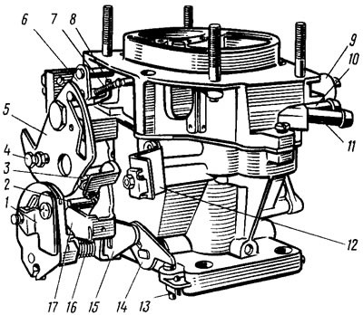
Pic. 15. Carburetor: 1 - sector with throttle control bracket; 2 - pin of the lock lever of the second chamber; 3 - adjusting screw for slightly opening the throttle valve of the first chamber; 4 - screw for fastening the air damper drive rod; 5 - air damper control lever; 6 - air damper lever; 7 - air damper return spring; 8 - a rod of diaphragms of the starting device; 9 - electromagnetic shut-off valve; 10 - fuel supply pipe; 11 - branch pipe for draining part of the fuel into the fuel tank; 12 - bracket for fastening the shell of the draft of the air damper drive; 13 - adjusting screw of the second chamber; 14 - throttle lever of the second chamber; 15 - throttle actuator lever of the second chamber; 16 - throttle return spring of the first chamber; / 7 - throttle control lever
The carburetor has two main dosing systems, a transition system and an idle system with an electromagnetic shut-off valve of the first chamber, a transition system of the second chamber, an econostat, a power mode economizer, a diaphragm accelerator pump, a starting device.
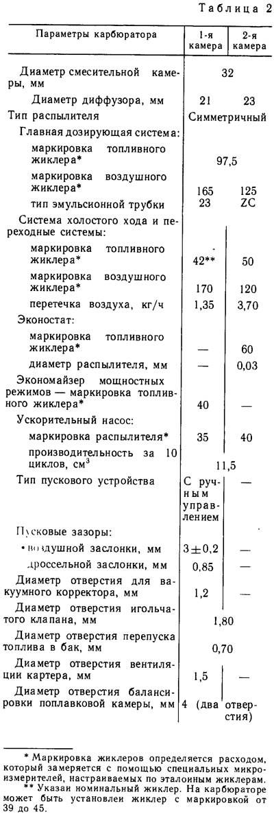
The main data of the carburetor are given in table. 2.
The main dosing system is powered from the float chamber, into which fuel enters through the needle valve 17 (pic. 16). Through the main fuel jets 28 and 38, the fuel enters the emulsion wells. With sufficient rarefaction in the atomizers of the main metering systems, the fuel is mixed in emulsion wells with air entering through air jets 6 and 13, and in the form of an emulsion is sucked into the diffusers of the mixing chambers. Only the main dosing system of the first chamber operates in throttling modes. The second chamber begins to open and operate when the throttle valve of the first chamber is more than two-thirds open.
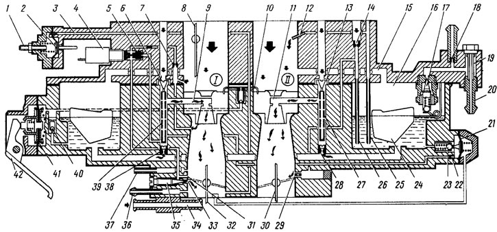
Pic. 16. Scheme of the carburetor: 1 - adjusting screw of the starting device; 2 - diaphragm of the starting device; 3 - air channel of the starting device; 4 - electromagnetic shut-off valve; 5 - idle fuel jet; 6 - main air jet of the first chamber; 7 - idle air jet; 8 - air damper; 9 - atomizer of the main dosing system of the first chamber; 10 - accelerator pump sprayers; 11 - atomizer of the main dosing system of the second chamber; 12 - econostat atomizer; 13 - main air jet of the second chamber; 14 - air jet of the transition system of the second chamber; 15 - float chamber balancing channel; 16 - float chamber; 17 - needle valve; 18 - calibrated hole for bypassing fuel into the tank; 19 - carburetor fuel filter; 20 - fuel supply pipe; 21 - diaphragm economizer power modes; 22 - fuel jet economizer power modes; 23 - ball valve of the economizer of power modes; 24 - float; 25 econostat fuel jet with tube; 26 - fuel jet of the transition system of the second chamber with a tube; 27 - emulsion tube of the second chamber; 28 - main fuel jet of the second chamber; 29 - outlet openings of the transition system of the second chamber; 30 - throttle valve of the second chamber; 31 - slot of the transition system of the first chamber; 32 - throttle valve of the first chamber; 33 - outlet of the idle system; 34 - carburetor heating block; 35 - quality adjusting screw (composition) idle mixtures; 36 - branch pipe for suction of crankcase gases; 37 - pipe for supplying vacuum to the vacuum ignition controller; 38 - main fuel jet of the first chamber; 39 - emulsion tube of the first chamber; 40 - ball valve of the accelerator pump; 41 - accelerator pump diaphragm; 42 - accelerator pump drive lever
The idle system provides the necessary composition of the combustible mixture at idle. In this case, the throttle valves 30 and 32 are closed. Fuel from the emulsion well of the main metering system rises through the fuel channel, passes through the fuel jet 5, mixes with air from the air jet 7 and the flow channel and then enters the quality screw 35 (composition) mixture into the throttle space.
The transition system of the first chamber provides a smooth transition of the engine from idling to throttling modes. At the moment of opening the throttle valve of the first chamber, the gap 31 of the transition system falls under vacuum; emulsion will also flow from it, providing a smooth transition.
When the ignition is turned off, the electromagnetic shut-off valve 4 is turned off, the needle closes the fuel jet 5 and prevents the engine from running with the ignition off.
The transitional system of the second chamber ensures a smooth transition of the engine operation at the moment the throttle valve of the second chamber begins to open. At this point, holes 29 are under vacuum; fuel from the float chamber through the jet 26 rises up the tube, air is mixed from the air jet 14 and the emulsion enters through the emulsion channel through the outlet holes under the throttle valve.
The econostat enriches the combustible mixture at fully open throttle valves at speeds close to maximum. With open throttle valves, the vacuum in the mixing chambers and sprayer 12 of the econostat increases significantly. Fuel from the float chamber enters through the jet 25 of the econostat and is sucked through the atomizer into the second mixing chamber.
The power mode economizer prevents changes in the degree of mixture enrichment due to vacuum pulsation under the throttle valve, especially when the crankshaft speed is reduced,"when the pulsation of rarefaction increases. The economizer ball valve 23 is closed as long as diaphragm 21 is held by vacuum under the throttle. With a significant opening of the throttle valve 32, the vacuum decreases slightly and the diaphragm spring opens the valve. The fuel passes through the valve, the economizer jet 22, is added to the fuel passing through the main fuel jet 38 and equalizes the enrichment of the mixture.
Accelerator pump - diaphragm type, driven by a cam on the axis of the throttle valve of the first chamber. With a sharp opening of the throttle valve, the cam presses the lever 42 and through the spring in the pusher acts on the diaphragm 41, overcoming the resistance of the return spring. The diaphragm delivers fuel through the supply ball valve and injects it through the atomizers 10 into the first and second mixing chambers. During the reverse stroke of the diaphragm, under the action of a return spring, fuel is sucked from the float chamber through the check ball valve 40 into the working cavity of the accelerator pump.
The starting device ensures the preparation of a rich combustible mixture when starting a cold engine. When turning lever 4 (pic. 17) the throttle valve 10 of the first chamber is slightly opened by the outer edge D of the adjusting screw 9. At the same time, the expanding groove between the internal profiles A and B of the lever 4 releases the pin of the lever 6 of the air damper, and it, due to the return spring 7, will be kept completely closed. The axis of the air damper 5 is displaced, therefore, after starting the engine, the air damper can be slightly opened by the air flow, stretching the spring 7, which ensures the lean mixture.
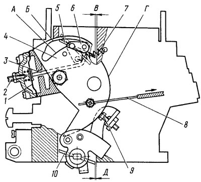
Pic. 17. Scheme of the starting device of the carburetor
The vacuum from the throttle space acts on the diaphragm 1 and can slightly open the air damper by the stem 3. Adjusting screw 2 allows you to adjust the amount of damper opening.
The overrun economizer disables the overrun idle system (during engine braking, when driving downhill, when shifting gears), excluding emissions of carbon monoxide into the atmosphere. In forced idle mode at a crankshaft speed of more than 2100 rpm and with the carburetor limit switch closed (pedal released) shut-off solenoid valve is switched off, the fuel supply is interrupted. When the crankshaft speed drops to 1900 rpm, the control unit turns on the electromagnetic shut-off valve (although the limit switch is closed), the fuel supply begins and the engine gradually comes to idle.
The throttle valve of the second chamber can only be opened when the air damper is fully open with the second chamber blocking lever pivotally mounted on lever 17 (see fig. 15). When the air damper is closed, the outer edge of the air damper control lever 5 retracts the second chamber lock lever behind the pin 2. In this case, only the throttle valve of the first chamber can open, the second chamber is blocked.
Possible engine malfunctions, their causes and remedies are given in tab. 3.