
- after removal of support 15 (pic. 100) compression buffer and unscrewing the nut 16 with a key 67.7811.9511, remove the working cylinder 22 with the rod 14 and its parts from the tank;
- the key 67.7824.9513-005 remove the guide sleeve 21 of the rod from the working cylinder, and then the piston with the rod and drain the liquid;
- using the techniques described when disassembling the front suspension strut, disassemble the compression and recoil valves and remove all parts from the stem.
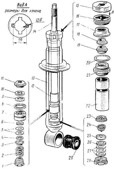
Pic. 100. Rear Suspension Shock Absorber Parts: 1 - recoil valve nut; 2 - recoil valve spring; 3 - recoil valve plate; 4 - washer, 5 - recoil valve discs, 6 - recoil valve throttle disc; 7 - piston; 8 - piston ring; 9 - bypass valve plate; 10 - bypass valve spring, 11 - restrictive plate; 12 - remote bushing; 13 - tank; 14 - stock; 15 - compression buffer support; 16 - nut; 17 - gasket; 18 - sewn rod ring; 19 - stuffing box; 20 - tank sealing ring; 21 - rod guide; 22 - cylinder; 23 - clip of the compression valve; 24 - intake valve spring; 21 - compression valve plate; 26 - throttle disc of the compression valve; 27 - compression valve disks; 28 - compression valve body; 29 - rubber-metal hinge
The assembly of the shock absorber is carried out in the reverse order, while the compression valve is pressed into the cylinder with the mandrel 67.7821.9513-004, and to facilitate the assembly of parts located on the rod, use the guide 67.7824.9513-003. The reservoir nut is tightened with a wrench 67.7824.9513-002 with a torque of 7 - 9 kgf-m.