These gaps are necessary in order to ensure the normal operation of the gas distribution mechanism during thermal expansion of parts.
When the engine is running, the valves are strongly heated by hot gases, their stems lengthen and the gaps decrease to almost zero. If there are no gaps on a cold engine or they are less than normal, then the valves will remain ajar on a running engine. This will lead to overheating and a sharp reduction in the durability of valves and seats, as well as a decrease in compression in the cylinders, and hence engine power. If the gaps are too large, shock loads and wear in the gas distribution mechanism will increase. The operation of the engine will be accompanied by knocks. Therefore, the adjustment of gaps must be given very serious attention.
To perform the adjustment, it is necessary to remove the air filter with a thermostat by disconnecting the crankcase ventilation system hose from the cylinder head cover, and the corrugated warm air supply hose from the warm air intake. Close the carburetor neck with a technological plug. Then disconnect the carburetor air and throttle control cables from the carburetor and cylinder head cover.
Remove the cylinder head cover by disconnecting the crankcase ventilation hoses from it. Remove the front toothed belt guard, remove the spark plugs and remove the oil from the oil baths of the cylinder head. Inspect the surfaces of the camshaft cams: they should not be scuffed or damaged in any way.
The gap must be adjusted in the following order:
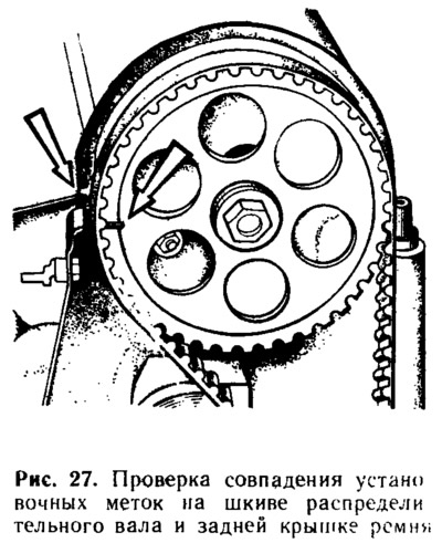
- turn the crankshaft until the alignment marks on the pulley and the back cover of the toothed belt are aligned (pic. 27), and then tighten it another 40...50° (2.5...3 teeth on the camshaft pulley); while in the first cylinder there will be a stroke of the working stroke;
- check the gaps at the 1st and 3rd camshaft cams with a set of probes (count the cam numbers in order from the camshaft pulley);
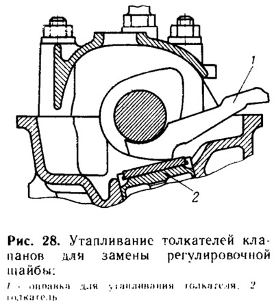
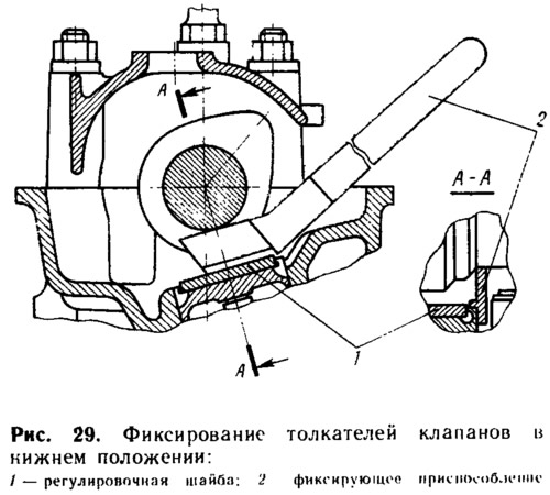
- if the gap differs from the norm, then turn the pusher with a slot towards you (slots are located at the top of the pusher) and drown the pusher with mandrel 1 (pic. 28), by inserting it between the camshaft journal and the shim. Fix the pusher in the lower position with tool 2 (pic. 29), by installing it between the edge of the pusher and the camshaft;
- remove the adjusting washer from the pusher with some device in the form of tongs with narrow jaws and measure its thickness with a micrometer;
- determine the thickness of the new washer using the formula:
H = B + (A - C),
where H is the thickness of the new washer; B is the thickness of the removed washer; A - measured gap; C is the nominal gap.
Example. Let's say A = 0.26 mm; B = 3.75 mm; C = 0.2 mm (for intake valve), Then:
H = 3.75 + (0,26 — 0,2) = 3.81 mm.
Within the clearance tolerance of±0.05 mm, we accept the thickness of the new washer equal to 3.8 mm.
- install a new adjusting washer in the pusher and remove the locking device; check the gap again. If it is adjusted correctly, then the probe with a thickness of 0.2 or 0.35 mm should enter with a slight pinch;
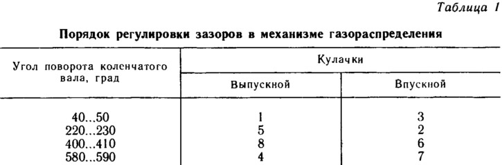
- sequentially turning the crankshaft half a turn, which corresponds to turning the mark on the camshaft pulley by 90°, adjust the clearances for the remaining valves, observing the sequence indicated in table. 1.
After completing the adjustment, add oil to the oil baths of the cylinder head, install the cylinder head cover and the front toothed belt cover. Install and adjust the carburetor air and throttle actuator (see «Power system maintenance»). Install the air filter.
When adjusting, the crankshaft should be turned only clockwise either by the crankshaft bolt or by the camshaft pulley with a lever-like device with two grips that fit into the pulley holes. It is not allowed to turn the crankshaft by the camshaft pulley bolt, as the bolt may be damaged.