
To perform the work you will need: a torque wrench, an inspection hole or overpass, a stop adjustable in height (e.g. screw jack), lifting device (hoist, hoist or winch with a load capacity of at least 100 kg) or a second adjustable stop. The work is best done with an assistant.
Comment. If there is no lifting device, the engine can be removed with two assistants. This requires a steel pipe with a diameter of 50-60 mm and a length of 2-2.5 m, as well as a cable.
Execution sequence
1. We prepare the car for work (see "Preparing the car for maintenance and repair").
2. With a bore gauge, we check the wear of the cylinder walls (see "Piston and connecting rod - replacement").
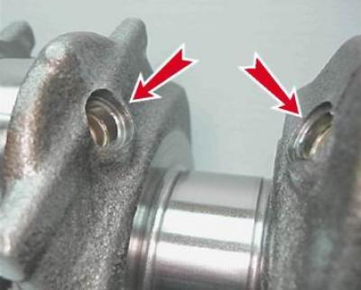
3. With a micrometer we check the wear of the connecting rod journals of the crankshaft (see below).
Comment. Further work is necessary in the presence of unacceptable wear of the block cylinders, connecting rod journals of the crankshaft, if there is a suspicion of wear of the crankshaft main journals or turning of the main bearing shells.
4. After loosening the clamp, remove the crankcase ventilation hose from the pipe of the cylinder block.
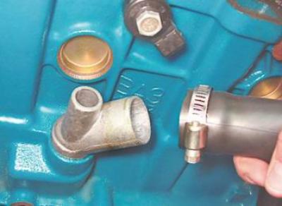
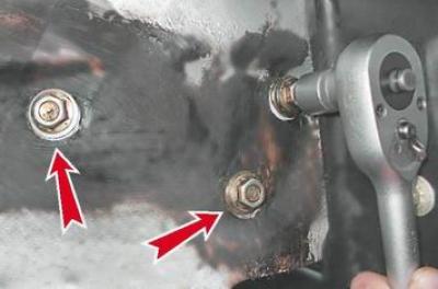
5. Key by 10 mm unscrew the two bolts securing the supply pipe to the cylinder block and disconnect it from the block.
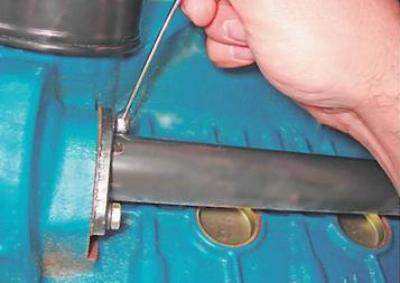
Comment. The connection is sealed with a gasket.
6. Remove the knock sensor (see "Knock sensor - check and replacement").
7. Remove the crankshaft position sensor (see "Crankshaft Position Sensor - Check and Replace").
8. Remove the coolant pump (see "Coolant pump - replacement").
9. Remove the starter (see "Starter - removal and installation").
10. Remove the generator (see "Generator - removal and installation").
Comment. On 16-valve engines, disconnect the lower engine mount from the front suspension cross member (see "Lower mount for engines 2112 and 21124 (16v)"), socket wrench by 17 mm unscrew the three bolts securing the lower bracket of the generator and remove the bracket assembly with the rod.
11. We install an adjustable stop under the gearbox and hang the cylinder block from the lifting device or install an adjustable stop under the cylinder block. Slightly raise the cylinder block, unloading the supports of the power unit.
12. Remove the bottom cover of the clutch housing and unscrew the bolts securing the gearbox to the cylinder block (see "Gearbox - removal and installation").
13. Turn off the upper nut of the right support cushion bolt (see "Right support").
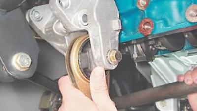
14. socket wrench by 13 mm unscrew the three bolts securing the bracket of the right engine mount to the cylinder block.
15. Remove the engine support bracket assembly with the upper generator mounting bracket.
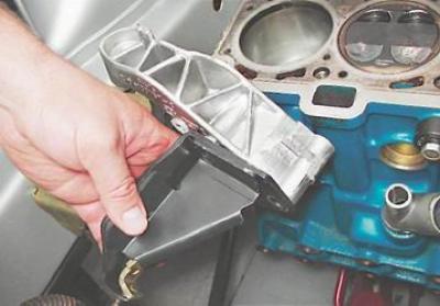
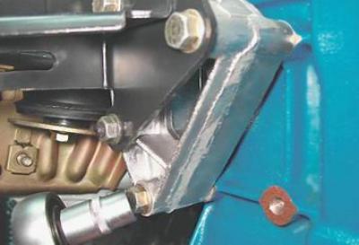
16. socket wrench by 15 mm under the right front fender of the car, unscrew the three bolts securing the support bracket to the right side member.
17. Remove the bracket together with the right support of the power unit.
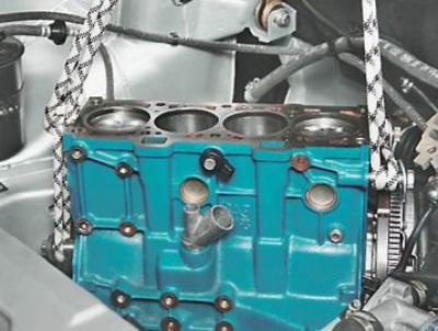
18. Slightly rocking the cylinder block, disconnect it from the gearbox and remove it from the engine compartment.
19. Remove the flywheel (see "Flywheel - removal and installation").
20. socket wrench by 10 mm unscrew the six bolts securing the crankshaft rear oil seal holder and remove it.
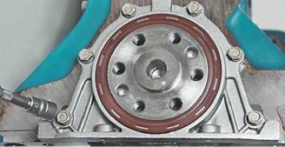
Comment. A gasket is installed under the holder, which must be replaced during assembly.
21. Remove the oil pump (see "Oil pump - removal, installation, assembly and disassembly").
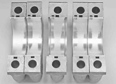
22. socket wrench by 17 mm unscrew the two bolts securing the five caps of the main bearings.
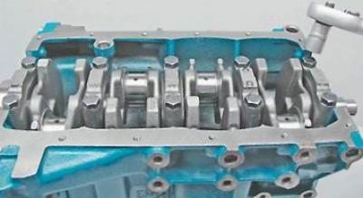
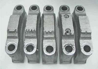
23. Remove the main bearing caps.
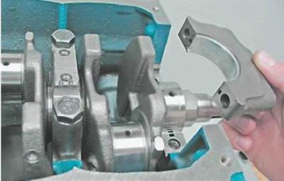
24. We take out the lower shells of the main bearings from the covers.
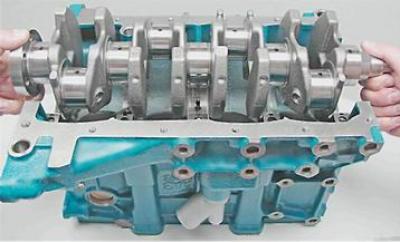
25. Remove the crankshaft from the cylinder block.
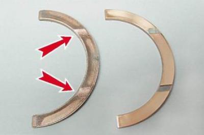
26. We take out two persistent half rings from the grooves of the third support.
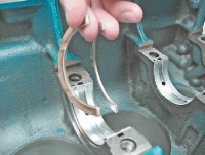
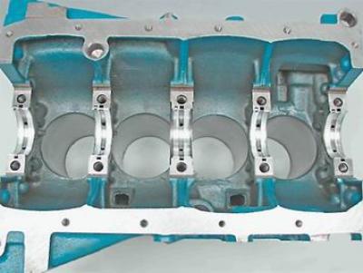
27. Remove the upper main bearing shells from the cylinder block supports.
28. We wash the cylinder block from dirt and deposits with a special detergent, diesel fuel or kerosene, and blow through the oil channels.
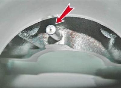
29. Clean the outlets of the oil nozzles with a thin copper wire on engines 2112, 21124 and 21114.
30. We wipe the block dry and inspect it. Cracks and chipping of metal are unacceptable.
31. We measure the main journals of the crankshaft with a micrometer, as well as (if this has not been done previously on the engine block installed on the vehicle) connecting rod necks.
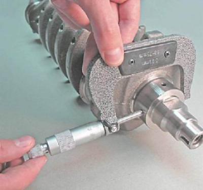
The crankshaft must be replaced or polished if the wear of its necks is more than 0.03 mm or the ovality of the necks is more than 0.03 mm, or there are scuffs and risks on the necks. It is possible to grind the shaft journals with a decrease in their diameter by 0.25; 0.5; 0.75 and 1.00 mm.
Table 8.2. Repair dimensions of the crankshaft journals, mm
|
Neck dimensions |
Indigenous necks |
crankpins |
|
Denomination |
50,799-50,819 |
47,83-47,85 |
|
1st renovation (-0,25) |
50,549-50,569 |
47,58-47,60 |
|
2nd renovation (-0,50) |
50,299-50,319 |
47,33-47,35 |
|
3rd repair (-0,75) |
50,049-50,069 |
47,08-47,10 |
|
4th repair (-1,00) |
49,799-49,819 |
46,83-46,85 |
Recommendation. If the engine cylinders have been bored, it is necessary to wash the cylinder block with diesel fuel or kerosene and blow it with compressed air, then wipe the shaft dry. After grinding the necks of the crankshaft of the engine, the plugs of the outlet holes of the channels should be removed. It is also necessary to wash the crankshaft with kerosene and blow the channels of the crankshaft with compressed air.
Warning! We install new plugs in the openings of the channels.
32. We select the appropriate rings, fingers and pistons (see "Selection of pistons to block cylinders"), as well as the crankshaft bearing shells (see above).
33. Degrease the nests of the liners in the supports and main bearing caps.
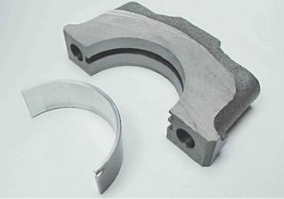
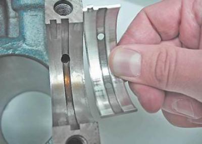
34. We put the liners of the main journals with grooves into the sockets of the supports.
35. We put liners without grooves in the bearing caps.
36. We install thrust half rings in the grooves of the third main support. Front side steel-aluminum (white on the inside and yellow on the outside), from the back - ceramic-metal (yellow on both sides).
Comment. Semi-rings are manufactured in nominal and increased by 0.127 mm thickness. The axial movement of the crankshaft should be within 0.06-0.26 mm.
37. We install half rings with grooves outward (to the cheeks of the crankshaft).
38. Lubricate the crankshaft journals and liners with clean engine oil.
39. We put the shaft in the cylinder block supports and install the main bearing caps.
Comment. Bearing numbers are marked on the covers (1st to 5th). The cover of the fifth main bearing is marked with two risks spaced to the edges of the cover.
When installed in the block, the covers must be marked with the marks facing the side of the block on which the oil level indicator guide is installed.
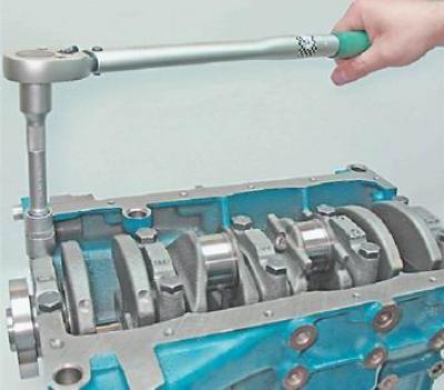
40. Tighten the cap bolts with a torque wrench to a torque of 68.31-84.38 N·m (6.97-8.61 kgf·m).
41. Further assembly is carried out in the reverse order.
Recommendation. If there is a suitable lifting mechanism, it is more convenient to assemble the cylinder block and then install it in the car.