
Remove the fuel supply hose from the fuel pump to the carburetor and the crankcase ventilation hose from the cylinder head cover to the carburetor. Remove the hose connecting the carburetor to the spark torque sensor vacuum regulator.
Disconnect the throttle linkage from the carburetor. Remove the carburetor with the gasket and the intake pipe with the gasket and with the bracket for the intermediate lever of the carburetor drive.
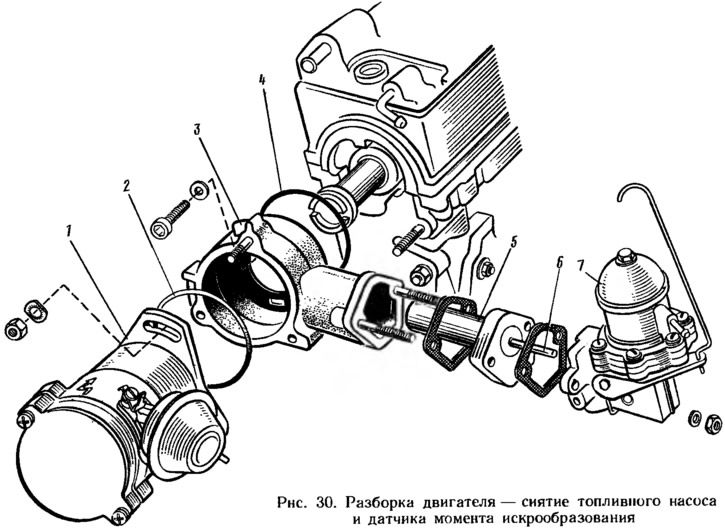
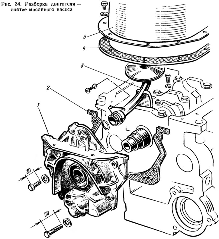
Remove sensor 1 (pic. thirty) the moment of sparking with a sealing ring 2, and then the fuel pump 7 together with a heat-insulating spacer 5, a pusher 6 and gaskets. Remove the housing 3 of the auxiliary units with the O-ring 4. If complete disassembly of the engine is not required, then the cylinder head assembly with the carburetor and auxiliary units can be removed.
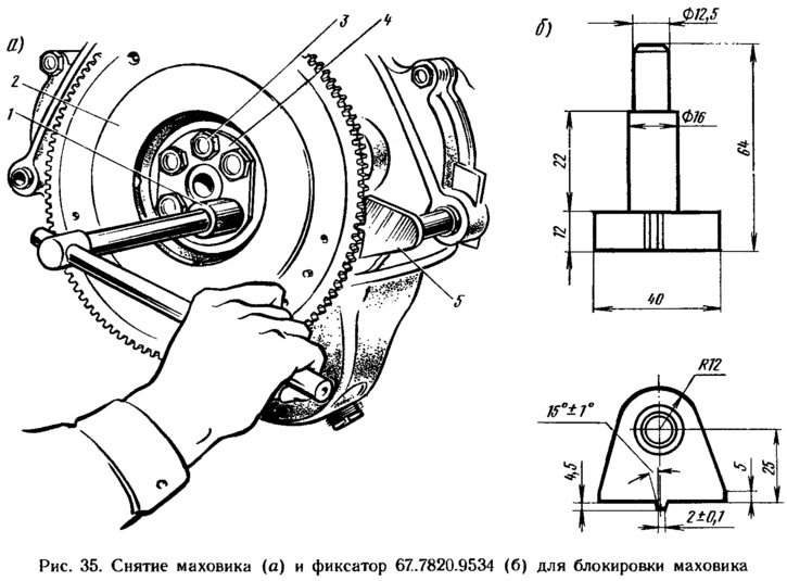
They remove the tension bar and the generator drive belt, and then the generator by unscrewing the bolt of its fastening to the bracket of the front suspension support of the power unit. Remove the front suspension support bracket of the power unit by unscrewing the mounting bolts. Block the flywheel with a latch 67.7820.9534 (see fig. 35), unscrew the bolt securing the alternator drive pulley and remove the pulley from the crankshaft.
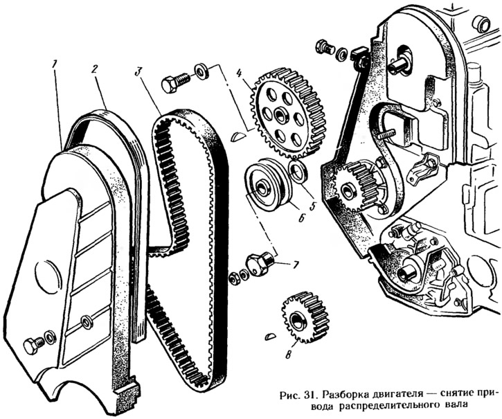
Remove front cover 1 (pic. 31) toothed belt with a rubber seal 2. Unscrew the nut securing the tension mechanism. Loosen and remove the toothed belt 3. Remove the tension roller 6 with the axis 7 and the distance ring 5. Holding the camshaft pulley 4 from turning with fixture 67.7811. 9513 behind the pulley holes, unscrew the fastening bolt and remove the pulley. Remove the toothed pulley 8 and the key from the crankshaft of the engine.
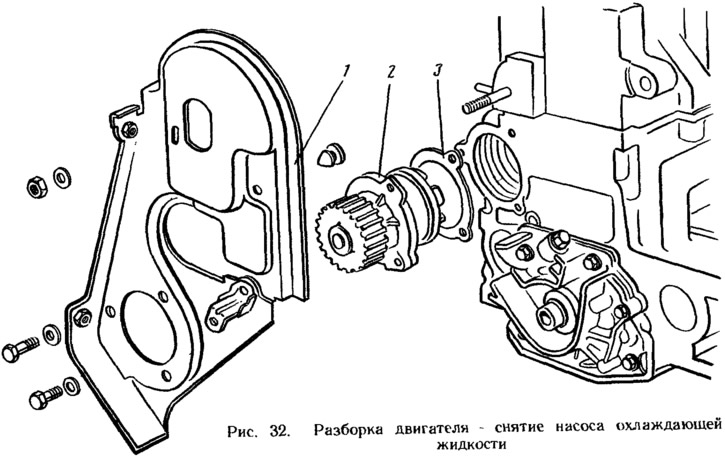
Loosen pump mounting bolts 2 (pic. 32) coolant. Unscrew the bolt and nut securing the rear cover 1 of the toothed belt and remove it together with the coolant pump and gasket 3.
Disconnect the hoses from the suction pipe 2 (see fig. 8) and outlet pipe 11 (see fig. 9) and remove the thermostat with hoses. Remove the coolant pump inlet pipe and outlet pipe with gasket. Key 67. 7812.9514 (tubular face 21 mm) unscrew the sensor of the coolant temperature indicator and spark plugs from the cylinder head.
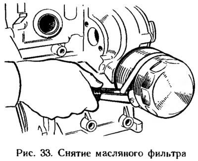
Tool A 60312 (pic. 33) remove the oil filter with gasket. Disconnect the crankcase exhaust ventilation hose from the nozzles on the cylinder head cover and on the crankshaft rear oil seal holder. Take out the oil level indicator.
Unscrew the oil pressure warning light sensor from the oil filter flange, and then remove the oil filter flange with gasket.
Remove the cylinder head cover with gasket and rubber bushings. Unscrew the cylinder head bolts and remove it complete with the camshaft. If necessary, disassemble the cylinder head, (see sect. «cylinder head»).
Turn the engine over with the crankcase up and remove the oil sump 5 (pic. 34) with gasket 4. Remove the oil receiver 3 and oil pump 1 with gasket 2. Unscrew the nuts of the connecting rod bolts, remove the connecting rod covers and carefully remove the pistons with connecting rods through the cylinders.
Block flywheel 2 (pic. 35) retainer 5 (67.7820.9534), with the key 1 unscrew the bolts 3 of the flywheel fastening, remove the washer 4 of the bolts and the flywheel from the crankshaft. Remove the crankshaft rear oil seal holder.
holding key «27» the middle part of the balance shaft from turning, unscrew the bolts securing the gears of the balance shafts and remove the gears. Remove the main bearing caps along with the lower bearings. The crankshaft is removed from the bearing seats, and then the upper shells and thrust half rings from the middle support.
Balance shafts are removed only if it is necessary to replace the shaft or its bearings. The removal of the shafts is described in sec. «Cylinder block» (see sect. «Dismantling and assembly of engine components»).