
You will need a multimeter to do the job.
Removing switches individually
1. We prepare the car for work and disconnect the wire terminal from the negative terminal of the battery (see "Car preparation for maintenance and repair").
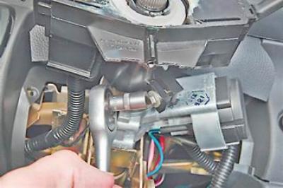
2. Remove the decorative lining of the steering column (see "Decorative overlays of a steering column - removal and installation").
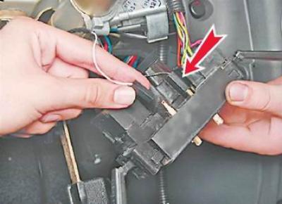
3. Squeezing the spring clips of the right switch, remove it from the connector together with the connected wiring harness block.
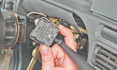
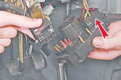
4. Disconnect the wiring harness block from the switch.
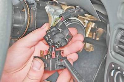
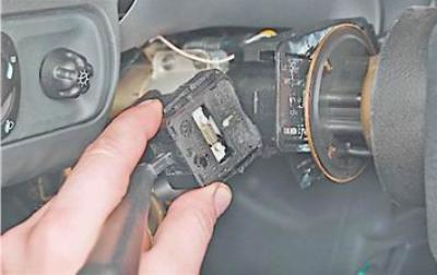
5. Similarly, remove the left steering column switch.
Examination
multimeter (in ohmmeter mode) we check the closure of the contacts in the switches at various positions of the switch lever.
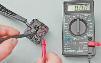
Note: The order of closing contacts for different positions of the switch levers is presented in table 13.9.1
Table 13.9.1. Closing of contacts at various positions of levers of understeering switches
|
Switch lever position |
Left switch |
Right switch |
||
|
Closed contact terminals* |
Switched electrical equipment |
Closed contact terminals* |
Switched electrical equipment |
|
|
1 |
49a-49aL |
Left turn indicator |
53e-53 |
Windshield wiper off |
|
2** |
49a-49aL |
Left turn indicator |
53e-53 |
Intermittent windshield wiper operation |
|
3 |
- |
Turn signals off |
53e-53 |
Intermittent windshield wiper |
|
56-56b |
dipped headlights |
|||
|
4** |
49a-49aR |
Right turn indicator |
53e-53 |
1st speed windshield wiper |
|
5 |
49a-49aR |
Right turn indicator |
53e-53 |
2nd speed windshield wiper |
|
6** |
30-56a |
High beam signaling |
53e-53 |
Windshield washer. Washer and headlight cleaner*** |
|
56-56b |
dipped headlights |
|||
|
7 |
56-56a |
high beam headlights |
53e-53 |
Rear window cleaner. |
|
8** |
- |
- |
53e-53 |
Rear window cleaner. |
|
53ah-WH |
Rear window washer. |
|||
* Pin designations are printed on the switch housing.
** Not fixed position.
*** Installed on some cars.
Setting switches
Install switches in reverse order of removal.
Removing Switch Assembly with Connector
1. Remove the steering wheel (see "Steering wheel - removal and installation").
2. Remove the decorative lining of the steering column (see "Decorative overlays of a steering column - removal and installation").
3. socket wrench by 8 mm unscrew the coupling bolt of the steering column switch connector by a few turns.
4. Remove the connector from the steering column.
5. Disconnect the pads of the two wires from the contacts of the horn switch.
6. Disconnect the two pads of the wiring harnesses from the steering column switches.
Installing the connector assembly with switches
1. In random order, we connect the pads of the two wires of the sound signal to the connector of the steering column switches.
2. We put the connector on the steering column.
3. Slightly tighten the coupling bolt of the connector (so that the position of the switch can be changed by hand).
Note: It is necessary to install the steering column switch connector in such a position that the central screw of the lower steering column trim can be screwed into the corresponding hole of the connector.
4. We install the lower trim of the steering column in place and use a Phillips screwdriver to wrap two screws securing the trim to the cross member of the instrument panel.
5. We adjust the position of the connector on the steering column, achieving the possibility of wrapping the central screw for fastening the steering column lining into the corresponding connector hole.
6. Having found the optimal position of the connector, unscrew the two screws and remove the lower trim of the steering column.
7. Without shifting the connector, we tighten the bolt of its fastening.
8. We carry out further work in the reverse order of removal.