
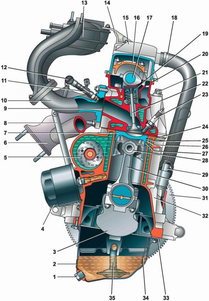
Cross section of engine 11183 (1,6i): 1 - drain plug of the oil pan; 2 - engine crankcase; 3 - crankshaft; 4 - oil filter; 5 - coolant pump; 6 - exhaust manifold; 7 - piston; 8 - rod for fastening the inlet pipeline; 9 - gasket of the inlet pipeline and exhaust manifold; 10 - inlet pipeline; 11 - nozzle; 12 - fuel rail; 13 - receiver; 14 - bracket; 15 - cylinder head cover; 16 - camshaft bearing housing; 17 - camshaft; 18 - hose of the crankcase ventilation system; 19 - valve pusher; 20 - cylinder head; 21 - a bolt of fastening of a head to the block of cylinders; 22 - valve; 23 - spark plug; 24 - cylinder head gasket; 25 - top compression ring; 26 - lower compression ring; 27 - oil scraper ring; 28 - piston pin; 29 - fitting for installing an oil dipstick; 30 - connecting rod; 31 - flywheel; 32 - cylinder block; 33 - gasket of the oil pan; 34 - oil dipstick; 35 - oil intake
The cylinder block is cast iron, with cylinders machined in it. The internal cavities of the block for the coolant are formed during its casting, and the oil supply channels are made by drilling. At the bottom of the block, five crankshaft main bearing supports are machined. The main bearing caps are machined with their bearings and are therefore not interchangeable. In order not to confuse the covers during installation, they are marked with the bearing serial number, starting from the crankshaft pulley. In the cover of the second main bearing, two threaded holes are made for the oil intake mounting bolts. Steel-aluminum liners are installed in the supports and caps of the main bearings. On both sides of the third main bearing support, sockets are made for installing thrust half rings that prevent axial movement of the crankshaft. Front half ring - steel-aluminum (yellow on one side, steel color on the other), rear - ceramic-metal (yellow on both sides).
The pistons are made of aluminum alloy, with steel rings poured into them. To prevent the pistons from hitting the valves when the timing belt breaks or its teeth are sheared, recesses for the valve plates are made in the bottom of each piston. Each piston has one oil scraper and two compression rings.
Fingers - floating type (fixed in the piston bores on both sides with snap rings). On part of the 2111 engines, a connecting rod and piston group of the 21083 engine can be installed, where the fingers are fixed in the upper heads of the connecting rods by the method "hot fit".
Connecting rods - steel, forged, with removable covers. The connecting rod caps are not interchangeable and only fit in one position to the connecting rods. The connecting rods and their caps are marked with the cylinder number.
From the bottom to the cylinder block, through the gasket, the oil pan is attached.
Combined engine lubrication system - under pressure and spray. The oil pump is an internal gear type driven by the front end of the crankshaft. Through the oil intake, the pump takes oil from the oil pan and pumps it under pressure into the channels of the engine lubrication system. To control the oil level in the sump, a measuring probe and an electric low oil level sensor are installed. The oil filter is full-flow, with a paper filter element and a check valve that prevents oil from flowing out of the lubrication system channels into the oil pan after the engine is stopped.
Channels are drilled in the body of the crankshaft. When the engine is running, oil under pressure from the block through the holes and grooves in the main bearing shells and the holes in the main journals enters the crankshaft channels and flows through them to the connecting rod journals, lubricating them. Technological openings of the channels are closed with stamped steel plugs.
The flywheel is bolted to the crankshaft flange. To connect them in the required position on the flywheel there is a mounting mark in the form of drilling, which should be opposite the connecting rod journal of the fourth cylinder.
On the left side of the block (when viewed from the side of the crankshaft pulley) a cavity is made for installing a coolant pump and a tide for installing an oil filter.
An aluminum head is installed on top of the cylinder block through a special gasket. It contains a camshaft, eight valves with guide bushings and seats, and eight valve lifters with shims. The camshaft bearings are made in the head. Two camshaft bearing housings are bolted to the upper plane of the head. From above, the gas distribution mechanism is closed with a cap with an oil filler neck. On some cars, a camshaft position sensor is installed in the cylinder head plug, and a pin is installed at the rear end of the shaft, designed to determine the shaft position sensor.
The camshaft and coolant pump are driven by a toothed belt from a toothed pulley mounted on the engine crankshaft. The tension of the belt and the direction of its movement along the pulleys is carried out by a tension roller. The generator is driven by a V-ribbed belt from the engine crankshaft pulley.
Features of the VAZ-11183 engine (1,6i)
Engine 11183, with a displacement of 1.6 liters, eight-valve, based on the VAZ-2111 engine. It has a cylinder block increased in height by 2.3 mm and an original crankshaft. The cylinder diameter remains the same - 82 mm, the piston stroke is increased to 75.6 mm against 71 mm for the base engine. Oil jets are installed in the main bearings. Oil from the nozzles is supplied to the internal surfaces of the pistons to cool them. Part of the oil falls on the upper heads of the connecting rods and flows through the conical holes made in them onto the piston pins, lubricating them.
The engine receiver 11183 is made of plastic. The original fuel rail without pressure regulator and injectors are installed on the engine, different from those used on the 2111 engine.