The layout of the engine is simple and easy to maintain. All engine components requiring adjustment or maintenance (ignition distributor, spark plugs, carburetor, air filter, chain tensioner, alternator, oil filter), installed in easily accessible places.
The engine cylinders are arranged vertically in a row, united together with the upper part of the crankcase and represent a single casting - cylinder block 3 (pic. 2), This arrangement ensures structural strength, rigidity, compactness, reliability and reduces the weight of the engine. The coolant channels are made along the entire height of the cylinders, which improves the cooling of the pistons and piston rings and reduces block deformation from uneven heating.
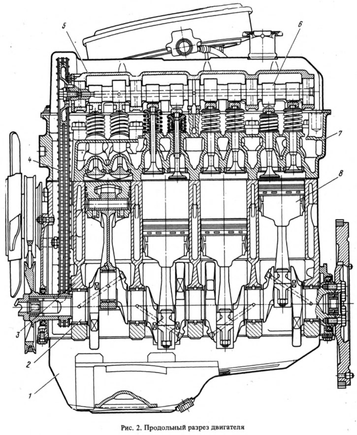
A crankshaft 2 is installed in the lower part of the cylinder block on five bearings. Due to the relatively large diameters of the main and connecting rod journals of the shaft, the specific loads on the bearings are small, so the crankshaft and its bearing shells have a sufficiently high durability. The front and rear ends of the crankshaft are sealed with self-clamping rubber seals.
In front of the cylinder block there is a cavity for accommodating the chain drive 4 of the camshaft 6. From the bottom, the cylinder block is closed with a steel stamped oil sump 1. Cork-rubber gaskets are also installed between the cylinder block and the camshaft cover.
Pistons 8 are cast from aluminum alloy and have two compression (sealing) and one oil scraper ring. Two steel plates are installed in the piston bosses during its casting. They compensate for the uneven thermal deformation of the piston, which occurs when it is heated in the engine cylinders due to the uneven distribution of the metal mass inside the piston skirt.
Cylinder head 7 - common to all cylinders. Cast iron guide bushings and valve seats are pressed into it. A metal-asbestos gasket is installed between the head and the cylinder block. A camshaft is installed on the cylinder head in a special housing 5, which is driven from the crankshaft by a double-row roller chain with a semi-automatic type tensioner. The drive from the camshaft to the valves is carried out through short levers 5 (pic. 3) without pushers, rods and rocker arms. Such a drive ensures accurate operation of the valves at high crankshaft speeds.
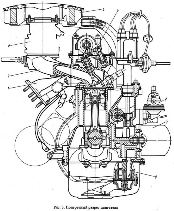
Engine lubrication system - combined (under pressure and spray); includes a full-flow oil filter 7 with a paper filter element through which all the oil passes. Oil pump 8 - gear.
The engine cooling system is liquid, closed type, with forced circulation of liquid and an expansion tank. The system is filled with a special coolant that freezes at low temperatures.
The power supply system includes: a fuel tank, a gasoline pump 6, an air filter 4, an inlet pipe 2, a carburetor 3 and an exhaust path. Pneumatic economizer equipment (econostat) and a diaphragm accelerator pump provides high acceleration, economy, confident start-up and stable operation of the engine immediately after start-up. The air filter is a dry type with a replaceable paper filter element with a layer of synthetic wool on the outside for air pre-cleaning. The filter is reliable in operation, provides high-quality air purification and does not require maintenance.
Exhaust tract includes exhaust manifold 1 and two puma exhaust mufflers (main and additional).
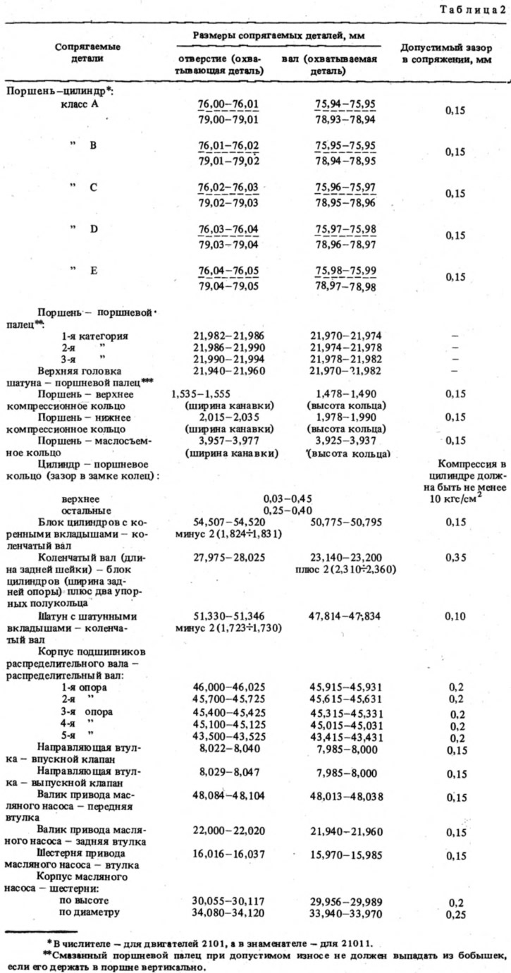
The dimensions of the main mating parts of the engine and the limits of allowable contributions in operation are given in Table. 2.