
bold lines show initial positions, thin lines show fixed positions, dotted lines show non-fixed positions of levers
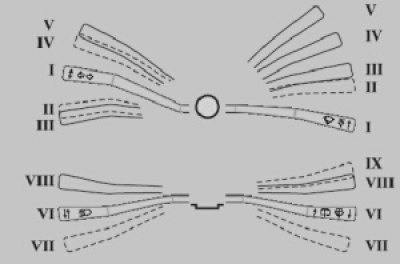
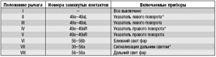
The serviceability of the steering column switches is determined by checking the correct closure of the contacts at various positions of the levers (see fig and table. at the end of the article).
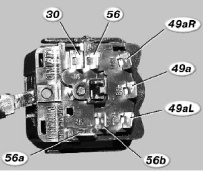
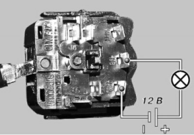
Numbers of contacts of the switch of indexes of turn and light of headlights of type 69.3709.
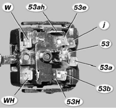
Numbers of contacts of the switch of a cleaner and washer of glasses of type 70.3709.
1. Remove the upper and lower facings of the steering column (see «Removal and installation of facings of a steering column»).
2. Remove the hazard switch (see «Hazard Switch Replacement»).
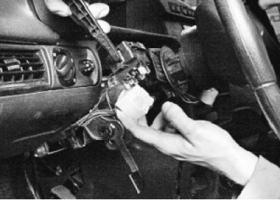
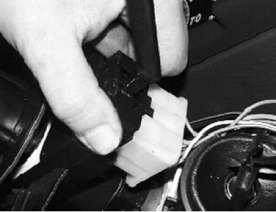
3. Squeezing the two plastic clips, remove the turn signal and headlight switch from the base of the steering column switches..
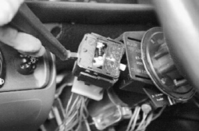
4.... and disconnect the wiring harness block from it.
5. Squeezing the two plastic clips, remove the wiper and washer switch from the base of the steering column switches and disconnect the wiring harness block from it.
6. For check of switches connect a control lamp on 12 V to the corresponding contacts specified in tab. 9.3 and 9.4 (in this case, checking the inclusion of the left turn signal is shown). Move the switch lever to the position corresponding to the contacts being tested - the lamp should light up. Otherwise, the switch is defective.
7. Establish understeering switches in an order, the return to removal.
Contact closure at different positions of the switch lever for direction indicators and headlights:
Contact closure at different positions of the wiper and washer switch lever:
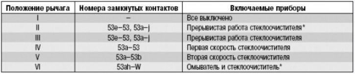
* Unfixed position.