
Motor switching circuit:
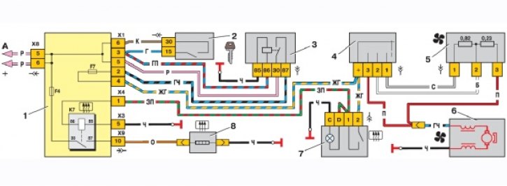
On the diagram of switching on the heater fan electric motor and rear window heating elements: 1 - mounting block; 2 - ignition switch; 3 - ignition switch unloading relay; 4 - heater motor switch; 5 - additional resistor; 6 - heater electric motor; 7 – the switch of heating of back glass with a control lamp of inclusion; 8 – an element of heating of back glass; K7 - rear window heating relay
An additional resistor is used to obtain a low speed. It is fixed with a screw on the left side of the heater core housing. The resistor includes two spirals: one with a resistance of 0.23 ohms, the second with a resistance of 0.82 ohms. When both spirals are connected to the electric motor power circuit, the first fan speed is provided; if a spiral with a resistance of 0.23 ohms is turned on - the second speed. When the electric motor is turned on without a resistor, the fan rotor rotates at maximum - the third speed (4100 min-1).
Data for checking the heater fan motor Shaft speed when the motor is loaded by the impeller (corresponds to a shaft load with a torque of 0.216 Nm (0.022 kgf·m)) at a voltage of 12 V and temperature (25±10) °C, min-1…..4100±200.
Consumed current at the specified load and speed, A, not more than.....14.