
English Русский
Български
Беларускі
Український
Српски
Hrvatski
Română
Polski
Slovenský
Magyar
| Articles | Contacts | Sitemap |   
Repair and maintenance Lada Repair and maintenance Mazda Repair and maintenance Mitsubishi Repair and maintenance Toyota Repair and maintenance Land Rover Repair and maintenance Hyundai Repair and maintenance Nissan
VAZbook.ru


Main     1111   2101   2105   2106   2107   2109   2110   2115   2121  
VAZ-2114 (2004-2013) VAZ-2115 (1997-2012)
  • Main
  • «Samara-2»
  • VAZ-2115
  • Electrical equipment
  • Equipment and devices
  • Removal, repair and installation of windshield wipers

Removal, repair and installation of windshield wipers (VAZ-2115)

            0

You will need: keys "10", "24", screwdriver.

1. Disconnect the wire from the "–" terminal of the battery.

2. Turn both brush levers to a vertical position and unscrew their mounting nuts.
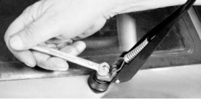
3. Remove the wiper arms from the wiper mechanism rollers
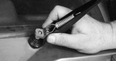

3. Remove the wiper arms from the wiper mechanism rollers

Note: If the lever cannot be removed by hand, loosen the lever mounting nut without completely…


Note: If the lever cannot be removed by hand, loosen the lever mounting nut without completely loosening it to avoid damaging the threads. Use pliers to pull the lever off the shaft splines, completely loosen the nut and remove the lever.


4. Remove one protective cap from both sides.
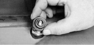
5. Unscrew one nut of the upper bracket mount on both sides.
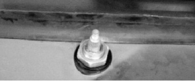

5. Unscrew one nut of the upper bracket mount on both sides.


6. Remove the rubber alignment washers from both sides.
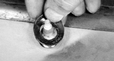

6. Remove the rubber alignment washers from both sides.

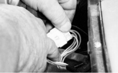
7. Open the hood and disconnect the windshield wiper wiring harness connector. Then move the heater…


7. Open the hood and disconnect the windshield wiper wiring harness connector. Then move the heater fan to the right along the compartment in front of the windshield (see "Removal and installation the heater fan"), otherwise it will interfere with the removal of the wiper.
8. Remove the cover of the relay and fuse box by pressing the cover latches.
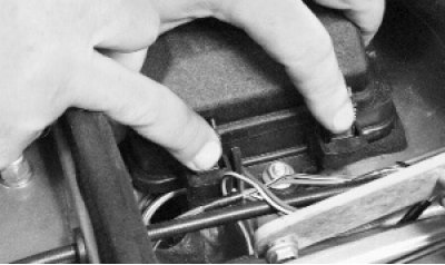

8. Remove the cover of the relay and fuse box by pressing the cover latches.


9. Remove all relays from the block so that they do not interfere with removing the windshield…


9. Remove all relays from the block so that they do not interfere with removing the windshield wiper.
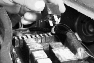
10. Remove the lower windshield wiper bracket mounting bolt.
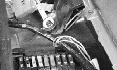

10. Remove the lower windshield wiper bracket mounting bolt.

11. Squeeze the plastic wire holder and remove it from the hole in the body.
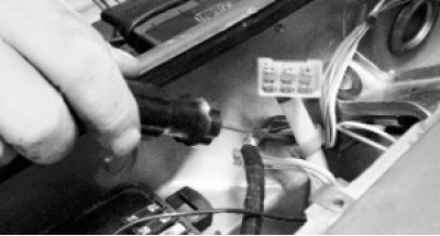

11. Squeeze the plastic wire holder and remove it from the hole in the body.

12. Remove the holder from the wires to avoid losing it.
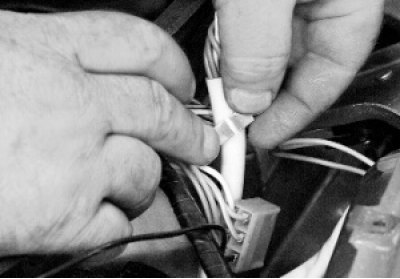

12. Remove the holder from the wires to avoid losing it.

13. Remove the windshield wiper mechanism rollers from the holes in the body.
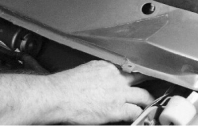

13. Remove the windshield wiper mechanism rollers from the holes in the body.

14. Move the windshield wiper so that its motor is in the wide part of the compartment in front of…


14. Move the windshield wiper so that its motor is in the wide part of the compartment in front of the windshield (heater fan installation location). Turn the windshield wiper and remove the windshield wiper motor from the compartment. Move the windshield wiper toward the relay and fuse box and remove it from the compartment.
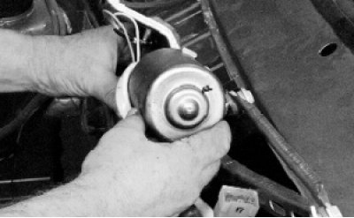
15. Loosen the windshield wiper mechanism crank mounting nut…
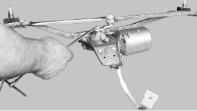

15. Loosen the windshield wiper mechanism crank mounting nut…

16. …and remove the crank from the gearbox shaft by prying it off with a screwdriver.
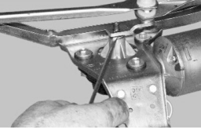

16. …and remove the crank from the gearbox shaft by prying it off with a screwdriver.

17. Unscrew the three bolts securing the gearbox to the electric motor.
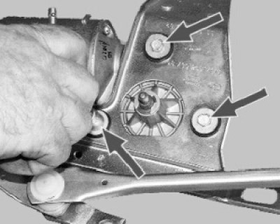

17. Unscrew the three bolts securing the gearbox to the electric motor.

18. Remove the two screws securing the electric motor wires and disconnect the wires from the…


18. Remove the two screws securing the electric motor wires and disconnect the wires from the thermal bimetallic fuse. Remove the motor from the bracket.
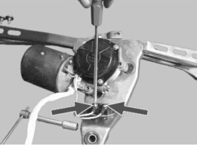
19. Remove the retaining ring from the gearbox shaft.
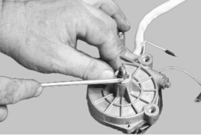

19. Remove the retaining ring from the gearbox shaft.

20. Remove the adjusting washers from the gearbox shaft.
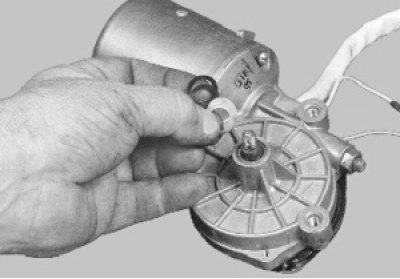

20. Remove the adjusting washers from the gearbox shaft.

Note: Mark the adjusting washers so that they are installed in the same places and in the same…


Note: Mark the adjusting washers so that they are installed in the same places and in the same quantity during assembly.


21. Remove the three mounting screws…
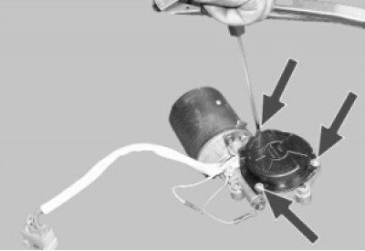
22. …and remove the gearbox cover.
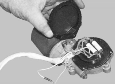

22. …and remove the gearbox cover.

Warning! When disassembling, do not unscrew the adjusting screw, otherwise the axial clearance of…


Warning! When disassembling, do not unscrew the adjusting screw, otherwise the axial clearance of the anchor shaft will be disturbed.
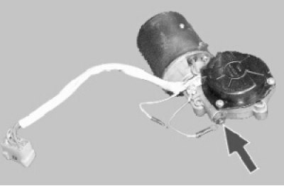

23. Remove the panel from the gearbox.
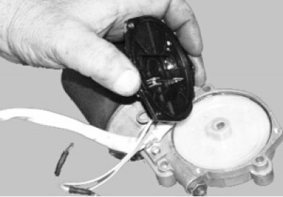

23. Remove the panel from the gearbox.

24. Remove the gear reducer.
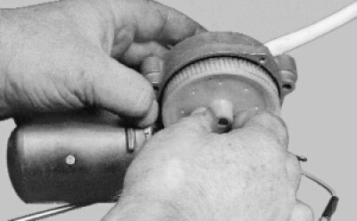

24. Remove the gear reducer.

25. Remove two screws (the second one is located behind the gearbox housing)…
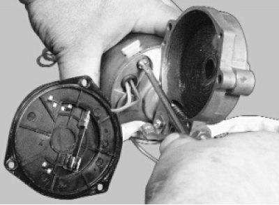

25. Remove two screws (the second one is located behind the gearbox housing)…

26. …and remove the two cap nuts.
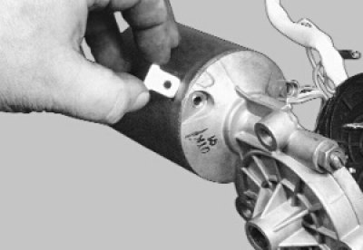

26. …and remove the two cap nuts.

27. Remove the gearbox housing with the brush holder from the electric motor housing.
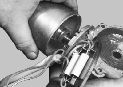

27. Remove the gearbox housing with the brush holder from the electric motor housing.

28. Remove the anchor from the motor housing. After disassembling, blow out the motor housing with…


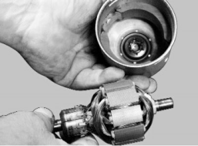
28. Remove the anchor from the motor housing. After disassembling, blow out the motor housing with compressed air to remove carbon dust.
29. Remove the retaining rings from both wiper mechanism rollers…
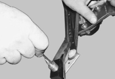

29. Remove the retaining rings from both wiper mechanism rollers…

30. …and adjusting washers.
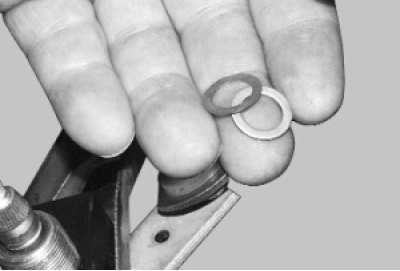

30. …and adjusting washers.

31. Remove the rods from the wiper bracket and remove the adjusting washers from both shafts.
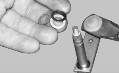

31. Remove the rods from the wiper bracket and remove the adjusting washers from both shafts.

32. Remove the sealing rings from the grooves on both sides of the bracket.
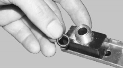

32. Remove the sealing rings from the grooves on both sides of the bracket.

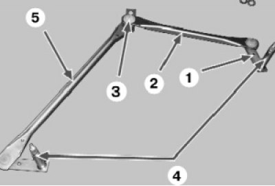
Note: Further disassembly of the rod system is not possible, since the rods are of a non-separable…


Note: Further disassembly of the rod system is not possible, since the rods are of a non-separable design: 1 - crank; 2 - short pull; 3 – rod joint; 4 – windshield wiper mechanism rollers; 5 – long pull.

33. If the brush springs are damaged or have lost elasticity, replace them.
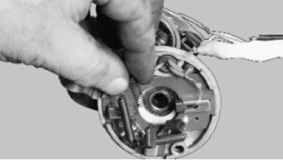

33. If the brush springs are damaged or have lost elasticity, replace them.

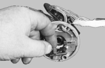
34. Check the ease of movement of the brushes in the brush holder. They should move freely, without…


34. Check the ease of movement of the brushes in the brush holder. They should move freely, without jamming. Replace worn or chipped brushes. When replacing, solder the terminals of the new brushes to the brush holder
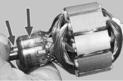
35. Clean the commutator with fine-grained sandpaper if it is dirty or has marks, scratches, etc.…


35. Clean the commutator with fine-grained sandpaper if it is dirty or has marks, scratches, etc. If the commutator is badly worn or burnt, replace the anchor or gearbox with the electric motor as an assembly. If traces of seizure are found on the anchor journals, clean the journals with fine-grained sandpaper.
36. Replace the gear reducer with badly worn or broken teeth.
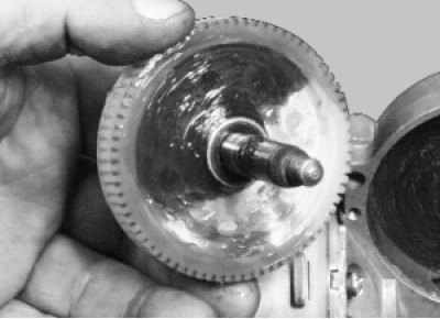

36. Replace the gear reducer with badly worn or broken teeth.

37. Straighten the bent rods. If this is not possible, replace the rods as an assembly.
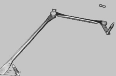

37. Straighten the bent rods. If this is not possible, replace the rods as an assembly.

38. If the splines or threads of the shafts are damaged, replace the rods as an assembly.
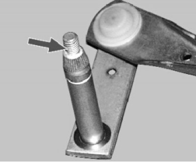

38. If the splines or threads of the shafts are damaged, replace the rods as an assembly.

39. Clean burnt or oxidized contacts of the self-stop mechanism with fine-grained sandpaper.


39. Clean burnt or oxidized contacts of the self-stop mechanism with fine-grained sandpaper.

40. Replace torn, cracked or loose rubber cushions and other rubber parts.

41. Assemble and install the windshield wiper in reverse order, taking into account the following:

The material is posted on the website: VAZBOOK.ru
  • make sure that when installing the anchor into the housing, the thrust ball is installed in the recess of the shaft;
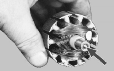
when assembling the gearbox, lubricate the gearbox gear and the worm shaft of the electric motor…

  • when assembling the gearbox, lubricate the gearbox gear and the worm shaft of the electric motor with consistent grease;
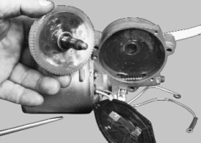
when installing the rods into the bracket, lubricate the rollers with consistent grease;
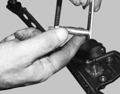
  • when installing the rods into the bracket, lubricate the rollers with consistent grease;

install the crank parallel to the short rod, it should be directed towards the electric motor.
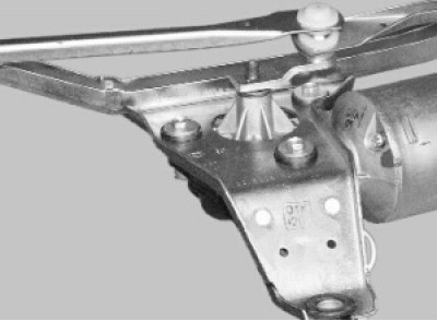
  • install the crank parallel to the short rod, it should be directed towards the electric motor.

42. Install the windshield wiper in the reverse order of removal.


42. Install the windshield wiper in the reverse order of removal.


This article is available at russian, bulgarian, belarusian, ukrainian, serbian, croatian, romanian, polish, slovak, hungarian
The text was reviewed by the specialist: Grigory Vologodtsev

Share with friends:

Previous articles
VAZ-2115: Equipment and devices
Next articles

Design features of windshield wipers and washers
Replacing the Horn Contact Ring
Adjusting and replacing the sound signal
Checking and replacing steering column switches
Replacing the ignition switch contact group
Removal, repair and installation of the rear window wiper
Removal and installation the washer reservoir
Electric motor of the heater fan
Removal and installation the heater fan
Disassembling the heater fan and repairing the electric motor

More articles from other manuals on VAZ cars:
➠ Replacing windshield wipers and cleaning washer jets VAZ-1111 (1988-1996)
➠ Windshield wiper repair VAZ-21011 (1974-1983)
➠ Windshield wiper repair VAZ-21051 (1979-2010)
➠ Windshield wiper repair VAZ-21061 (1976-2006)
➠ Windshield wiper gear motor repair VAZ-2108 (1984-2003)
Link in different formats to this page


Visitor comments

No comments yet


How much will 12 + 18 ?


VAZ-2114 (2004-2013) 
  • General information
  • Operation and maintenance
  • Power unit
  • Engine repair
  • Cooling system
  • Supply system
  • Control system
  • Exhaust system
  • Transmission
  • Clutch
  • Car gearbox
  • Front wheel drives
  • Chassis
  • Wheels and tires
  • Front suspension
  • Rear suspension
  • Steering
  • Brake system
  • Body
  • Exterior
  • Interior
  • Doors and glass
  • Tailgate
  • Ventilation and heating
  • Electrical equipment
  • Equipment and devices
  • Headlights and lighting
  • Engine electrics
  • Electrical circuits


VAZ-2115 (1997-2012) 
  • General information
  • Vehicle device
  • Operation manual
  • Vehicle malfunctions
  • Car care
  • Power unit
  • Engine repair
  • Cooling system
  • Supply system
  • Control system
  • Exhaust system
  • Transmission
  • Clutch
  • Car gearbox
  • Front wheel drives
  • Chassis
  • Front suspension
  • Rear suspension
  • Steering
  • Brake system
  • Body
  • Exterior
  • Interior
  • Doors, covers and windows
  • Electrical equipment
  • Equipment and devices
  • Headlights and lighting
  • Engine electrics
  • Anti-theft system


VAZbook.ru © 2017 · Mobile version · Contact with administration · Sitemap: EN BG BY UA RS HR RO PL SK HU · Site search · News and articles VAZ-1111 · VAZ-11113 · VAZ-2101 · VAZ-21011 · VAZ-2104 · VAZ-2105 · VAZ-21051 · VAZ-2106 · VAZ-21061 · VAZ-2107 · VAZ-21099 · VAZ-2109 · VAZ-2108 · VAZ-2110 · VAZ-2112 · VAZ-2114 · VAZ-2115 · VAZ-2121 · VAZ-21213 · VAZ-21214 ·
The site stores technical data using cookies to improve the service.