
The ignition lock is equipped with an anti-theft locking device, a starter re-engagement blocking when the engine is running, and illumination of the lock slot.
The locking rod of the anti-theft device extends when the key is removed from the lock (key can only be removed in position «0»). When turning the key from position «0» into position «I» locking rod retracts inside the lock, contacts «30» and «15» ignition switches are closed.
When the key is turned to position «II» voltage is applied to the starter relay. From this position, the key automatically returns to the position under the action of the spring «I». Turn the key back to position «II» possible, only by first turning it to the position «0».
Ignition Switch Wiring Diagram (with key inserted):
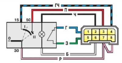
The circuits that close at different key positions are shown in the table below. Circuit breaker connection diagram (castle) ignition is shown in the upper figure.
| Key position | Live contacts | Switched circuits |
| 0 (turned off) | 30 | — |
| I (ignition) | 30-15 | Ignition system, generator excitation, headlights, turn signals, control instruments, windshield wipers and washers, heater fan motor, heated rear window, cigarette lighter |
| II (starter) | 30-15 30-50 |
See "I" position starter |