
There are two types of distributed injection systems - with and without feedback. Moreover, systems of both types can be with imported components or with domestic ones. Install controllers (electronic control units) also different types. All these systems have their own characteristics of the device, diagnostics and repair, they are described in detail separately in the relevant repair manuals for specific fuel injection systems.
The following ECM can be installed on cars of the LADA SAMARA-2 family, which ensure compliance with toxicity standards.
- 1. ECM-2111, which ensures compliance with Russian toxicity standards, with the M1.5.4 controller and, more recently, with the controller «January-5.1.1» (these controllers are interchangeable, although they have slight differences in diagnostics). The latter is distinguished by the absence of a fuel vapor adsorber in the engine compartment and the round shape of the mass air flow sensor (Bosch).
- 2. ECM-2111, which ensures compliance with the EURO II toxicity standards, with the MP7.0HFM controller.
- 3. ECM-2111, ensuring compliance with EURO II toxicity standards, with controllers M1.5.4N and «January-5.1». The system, intended for completing cars of the domestic market of Russia, is constantly being upgraded: diagnostics of output circuits has been introduced for the latest versions of the software.
If the vehicle is equipped with a feedback system (used mainly on export vehicles), a converter and an oxygen concentration sensor are installed in the exhaust system, which provides feedback. The sensor monitors the concentration of oxygen in the exhaust gases, and the electronic control unit, based on its signals, maintains the ratio of air and fuel, which ensures the most efficient operation of the converter.
In an open-loop injection system, a converter and an oxygen concentration sensor are not installed, and a CO potentiometer is used to adjust the CO concentration in the exhaust gases. This system also does not use a gasoline vapor recovery system.
A variant of the injection system is also possible without a CO potentiometer, in which case the CO content is adjusted using a diagnostic tool.
Warnings:
1. Before removing any components of the injection control system, disconnect the wire from the terminal «–» battery.
2. Do not start the engine if the battery terminals are loose.
3. Never disconnect the battery from the car's on-board network when the engine is running.
4. When charging the battery, disconnect it from the car's on-board network.
5. Do not expose the electronic control box (ECU) temperature above 65°C in working condition and above 80°C in non-working condition (e.g. in a drying chamber). It is necessary to remove the computer from the car if this temperature is exceeded.
6. Do not disconnect or connect the wire harness connectors to the ECU while the ignition is on.
7. Before performing arc welding on a vehicle, disconnect the wires from the battery and the wire connectors from the ECU.
8. Perform all voltage measurements with a digital voltmeter with an internal resistance of at least 10 MΩ.
9. The electronic components used in the injection system are designed for very low voltage and therefore can be easily damaged by electrostatic discharge. To prevent ECU damage from electrostatic discharge:
- do not touch the computer plugs or electronic components on its boards with your hands;
- when working with PROM (programmable read only memory) control unit, do not touch the microcircuit pins.
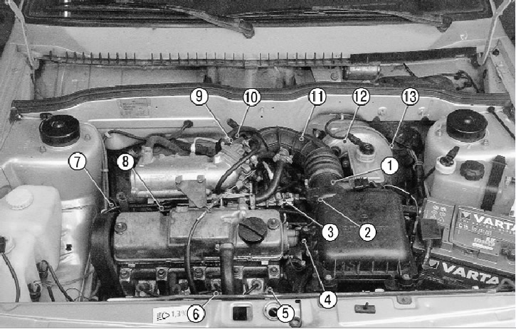
9.12. Location in the engine compartment of the elements of the engine management system with distributed fuel injection without feedback: 1 - mass air flow sensor; 2 - speed sensor (not visible in the photo, located on the gearbox); 3 - pressure regulator; 4 - coolant temperature sensor (not visible in the photo, located on the outlet pipe of the cooling system); 5 - ignition module; 6 - knock sensor; 7 - crankshaft position sensor (not visible in the photo, located in the tide of the oil pump cover); 8 - fuel rail with nozzles; 9 - throttle position sensor; 10 - idle speed regulator (not visible in the photo, located on the throttle assembly); 11 - controller (not visible in the photo, located in the passenger compartment under the instrument panel on the bracket); 12 - fuses and relays of the engine management system (not visible in the photo, located in the passenger compartment under the instrument panel on the right side); 13 - diagnostic connector (not visible in the photo, located in the passenger compartment on the dashboard panel under the ashtray)
The ignition system uses an ignition module 5 (pic. 9.12), consisting of two ignition coils and high energy control electronics. The ignition system has no moving parts and therefore requires no maintenance. It also has no adjustments, since the ignition is controlled by the controller 11.
The ignition system uses a spark distribution method called the spark distribution method «idle spark». The engine cylinders are combined in pairs 1-4 and 2-3, sparking occurs simultaneously in two cylinders: in the cylinder in which the compression stroke ends (working spark), and in the cylinder in which the exhaust stroke occurs (idle spark). Due to the constant direction of the current in the windings of the ignition coils, the sparking current in one candle always flows from the central electrode to the side, and in the second - from the side to the central one. Candles of type A17DVRM are used. The controller 11 controls the ignition in the system. The crankshaft position sensor 7 supplies the controller with a reference signal, on the basis of which the controller calculates the sequence of operation of the coils in the ignition module. To precisely control the ignition, the controller uses the following information:
- crankshaft speed;
- engine load (mass air flow);
- coolant temperature;
- crankshaft position;
- presence of detonation.
The engine management system is described in more detail in a special publication «Engine control systems VAZ-2111 (1.5 l, 8 cells), VAZ-2112 (1.5 l, 16 cells), VAZ-21214-36 (1.7 l, 8 cells) with distributed sequential fuel injection (MP7.0NFM controller, Euro-3 toxicity standards) cars VAZ-21083, 21093, 21099, 21102, 21103, 2111, 21113, 2112, 21122, 21214. Diagnostic and repair manual» (series «Master Class»), prepared by the Directorate for Technical Development of JSC «AVTOVAZ» and published in 2004. «Publishing House Third Rome». The same manual describes methods for diagnosing the system by trouble codes using the DST-2 diagnostic tool.
The engine management system includes the following elements.
1. Controller 11 (see fig. 9.12) (electronic control unit), located under the instrument panel shield on the bracket, is the control center of the fuel injection system. It continuously processes information from various sensors and manages systems that affect exhaust emissions and vehicle performance.
The controller receives the following information:
- position and frequency of rotation of the crankshaft;
- mass air consumption by the engine;
- coolant temperature;
- throttle position;
- exhaust oxygen concentration (in a feedback system);
- the presence of detonation in the engine;
- voltage in the vehicle's on-board network;
- vehicle speed;
- camshaft position (in a system with sequential distributed fuel injection);
- request to turn on the air conditioner (if it is installed on the car).
Based on the information received, the controller controls the following systems and devices:
- fuel supply (injectors and electric fuel pump);
- ignition system;
- idle control;
- adsorber of the gasoline vapor recovery system (if this system is installed on the car);
- engine cooling fan;
- air conditioning compressor clutch (if it is installed on the car);
- diagnostic system.
The controller turns on the output circuits (nozzles, various relays, etc.) by closing them «mass» through the output transistors of the controller. The only exception is the fuel pump relay circuit. The controller supplies +12 V only to the winding of this relay.
The controller is equipped with a built-in diagnostic system. It can recognize malfunctions in the system, warning the driver about them through a warning lamp «Check Engine». In addition, it stores diagnostic codes indicating fault areas to assist technicians in carrying out repairs. The controller has three types of memory: RAM (RAM), one-time programmable read-only memory (PROM) and electrically programmable memory (EPROM).
Working memory is «notebook» controller. The microprocessor of the controller uses it to temporarily store measured parameters for calculations and intermediate information. The microprocessor can enter data into it or read them out as necessary. The RAM chip is mounted on the controller PCB. This memory is volatile and requires an uninterruptible power supply to maintain. When the power supply is interrupted, the diagnostic trouble codes and calculated data contained in the RAM are erased.
Programmable Read Only Memory (PROM). It contains a general program, which contains a sequence of working commands (control algorithms) and various calibration information. This information is injection, ignition, idle control data, etc., which depend on vehicle weight, engine type and power, transmission ratios, and other factors. PROM is also called a calibration memory. The contents of the PROM cannot be changed after programming. This memory does not need power to save the information recorded in it, which is not erased when the power is turned off, i.e. this memory is non-volatile. The PROM is installed in a socket on the controller board and can be removed from the controller and replaced.
PROM is individual for each vehicle configuration, although the same unified controller can be used on different car models. Therefore, when replacing the PROM, it is important to set the correct model number and vehicle equipment. And when replacing a defective controller, you must leave the old PROM (if it is correct).
An electrically programmable memory is used to temporarily store vehicle anti-theft system passwords (immobilizer). Password codes received by the controller from the immobilizer control unit (if it is on the car), are compared with the codes stored in the EEPROM, and at the same time, the engine start is allowed or prohibited. This memory is non-volatile and can be stored without power to the controller.
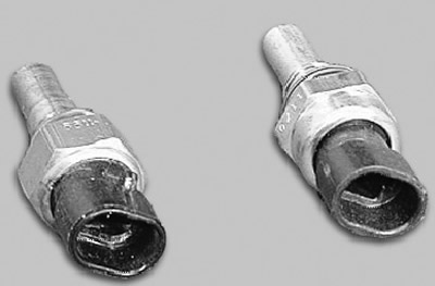
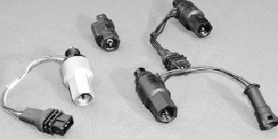
2. Coolant temperature sensor 4 is a thermistor (resistor whose resistance changes with temperature). The sensor is screwed into the coolant outlet on the cylinder head. At low temperature, the sensor resistance is high (at -40°С - 100 kOhm), at high temperature - low (at 100°С - 177 Ohm).
The controller calculates the coolant temperature from the voltage drop across the sensor. The voltage drop is high on a cold engine and low on a warm one. The coolant temperature affects most of the characteristics controlled by the controller.
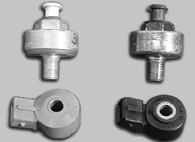
3. Knock sensor 6 is attached to the top of the cylinder block. It picks up abnormal vibrations (detonation strikes) in the engine.
The sensitive element of the sensor is a piezoelectric plate. During detonation, voltage pulses are generated at the output of the sensor, which increase with increasing intensity of detonation impacts. The controller, based on a sensor signal, regulates the ignition timing to eliminate detonation fuel flashes.
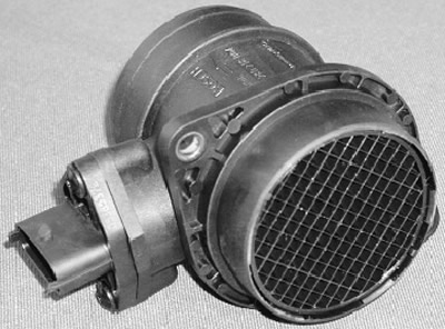
4. Mass air flow sensor 1 from Bosch or…
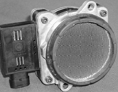
…GM is located between the air filter and intake pipe hose. It contains temperature sensors and a heating resistor. The passing air cools one of the sensors, and the sensor electronics convert this temperature difference into an output signal for the electronic control unit. In different versions of fuel injection systems, it is possible to use two types of mass air flow sensors. They differ in the device and the nature of the output signal, which can be frequency or analog. In the first case, depending on the air flow, the signal frequency changes, in the second case, the voltage. The ECU uses information from the mass air flow sensor to determine the duration of the injector opening pulse.
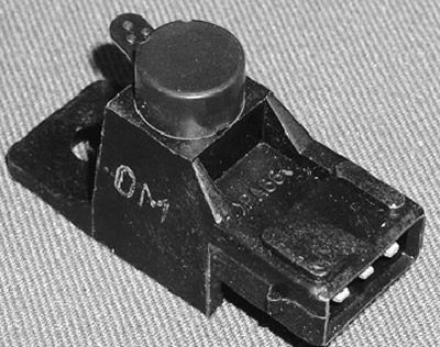
5. CO-potentiometer installed on cars with injection system without feedback (without converter and oxygen concentration sensor) in the engine compartment and is a variable resistor. It sends a signal to the ECU, which is used to adjust the air-fuel mixture in order to obtain a normalized level of carbon monoxide concentration (SO) in exhaust gases at idle. The CO potentiometer is like the mixture screw in carburetors. Adjustment of the CO content using a CO potentiometer is only carried out at a service station using a gas analyzer.
6. Vehicle speed sensor installed on the gearbox. The principle of operation of the sensor is based on the Hall effect. The sensor outputs rectangular voltage pulses to the controller, the frequency of which is proportional to the speed of rotation of the driving wheels.
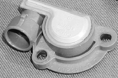
7. Throttle position sensor 9 is mounted on the side of the throttle pipe and is connected to the throttle valve axis.
The sensor is a potentiometer, one end of which is supplied with «+» supply voltage (5 V), its other end is connected to «weight». From the third output of the potentiometer (from the slider) is an output signal to the controller. When the throttle is turned (from impact on the control pedal), the voltage at the output of the sensor changes. When the throttle is closed, it is lower than 0.7 V. When the throttle opens, the voltage at the sensor output rises and should be more than 4 V when the throttle is fully open. By monitoring the output voltage of the sensor, the controller adjusts the fuel supply depending on the throttle opening angle (those. at the request of the driver).
Throttle position sensor does not require any adjustment as the controller senses idling (those. full throttle closing) as a zero point.
8. Idle speed regulator 10 regulates the idle speed by controlling the amount of air supplied to bypass the closed throttle. It consists of a two-pole stepper motor and a cone valve connected to it. The valve extends or retracts according to the controller signals.
Fully extended regulator needle (which corresponds to 0 steps) blocks the air flow. When the needle is retracted, an air flow is provided that is proportional to the number of steps the needle moves away from the seat.
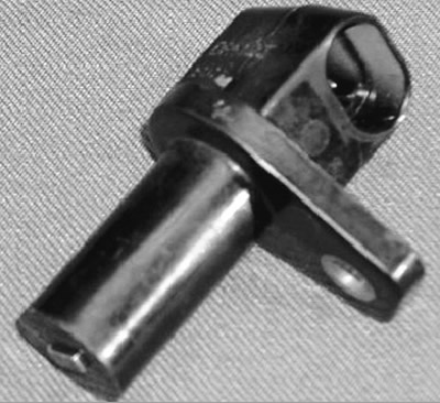
9. Crankshaft position sensor 7 - inductive type, designed to synchronize the operation of the controller with the TDC of the pistons of the 1st and 4th cylinders and the angular position of the crankshaft.
The sensor is mounted on the cover of the oil pump opposite the drive disk on the alternator drive pulley. The driving disk is a gear wheel with 58 equidistant (6°) depressions. This pitch fits 60 teeth on the disc, but two of the teeth are sheared off to create a timing pulse («reference» momentum), which is necessary to coordinate the operation of the controller with the TDC of the pistons in the 1st and 4th cylinders. As the crankshaft rotates, the teeth change the sensor's magnetic field, inducing AC voltage pulses. The installation gap between the sensor core and the disc tooth must be within (1±0,2) mm.
The controller determines the crankshaft speed from the sensor signals and sends pulses to the injectors.
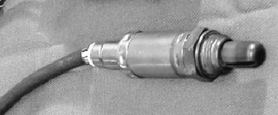
10. Oxygen concentration sensor (Lambda probe) used in the injection system with feedback and installed on the exhaust pipe of silencers. The oxygen contained in the exhaust gases reacts with the sensor, creating a potential difference at its output, which varies from approximately 0.1 V (high oxygen content - lean mixture) up to 0.9 V (little oxygen - rich mixture).
For normal operation, the temperature of the sensor must be at least 360°C. Therefore, to quickly warm up the engine after it is started, a heating element is built into the sensor.
By monitoring the output voltage of the oxygen concentration sensor, the controller determines which command to adjust the composition of the working mixture to apply to the injectors. If the mixture is lean (low potential difference at the sensor output), then a command is given to enrich the mixture. If the mixture is rich (high potential difference), the command is given to lean the mixture.