




Cooling system
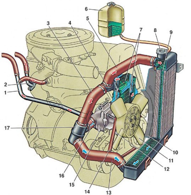
1 – pipe for draining liquid from the heater radiator and carburetor to the coolant pump; 2 – pipe for draining hot liquid from the cylinder head to the heater radiator; 3 – thermostat bypass hose; 4 – cooling jacket outlet pipe; 5 – radiator supply hose; 6 – expansion tank; 7 – cooling jacket; 8 – radiator cap; 9 – radiator; 10 – fan casing; 11 – fan; 12 – fan and coolant pump drive pulley; 13 – radiator drain hose; 14 – pump drive belt; 15 – pump; 16 – coolant supply hose to the pump; 17 – thermostat;
The arrows indicate the direction of fluid movement.
The cooling system is liquid, closed type, with forced circulation of liquid, with an expansion tank.
Attention! It is recommended to check the coolant level on a cold engine, since when heated its volume increases, and the coolant level on a warm engine can rise significantly.
The coolant pump is of the centrifugal type, driven from the crankshaft pulley by V-belt 14.
Fan 11 has a plastic four-blade impeller mounted on the hub of the coolant pump pulley.
Thermostat 17 with a solid heat-sensitive filler has a main 9 (see Fig. Thermostat) and additional 2 valves. The main valve starts to open at a coolant temperature of 77–86°C, the main valve stroke is not less than 6 mm.
The radiator is vertical, tubular-plate, with two rows of tubes and tinned steel plates. There are inlet and outlet valves in the plug 8 of the filler neck.