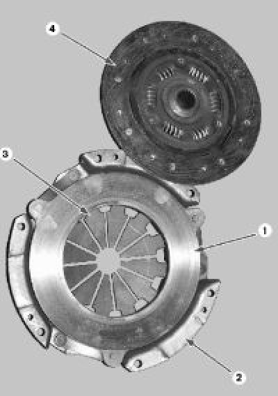
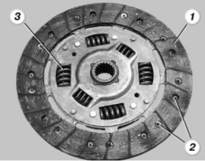
Disassembled clutch: 1 - pressure plate; 2 - clutch cover; 3 - diaphragm spring; 4 - driven disk
1. Remove the gearbox from the car (see «Removal and installation of a transmission»).
2. Install the mandrel in the hole of the hub of the driven disk 4
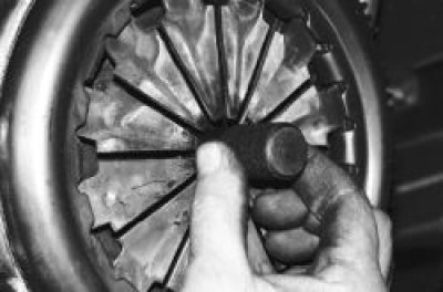
Note. You can remove the clutch without a mandrel, but at the same time hold the driven disk - it may fall out of the clutch housing.
Helpful advice. The mandrel for centering the driven disk can be made according to the dimensions of the input shaft, or an old input shaft can be used instead.
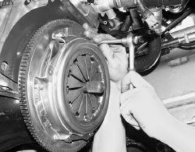
3. Turn out six bolts of fastening of a casing of coupling. Remove the clutch cover assembly with the pressure plate and driven plate installed inside the casing. Hold the driven disk so that it does not fall out.
Note.
When loosening the clutch cover mounting bolts, block the flywheel with a screwdriver. To stop the screwdriver, install one bolt of the clutch housing (for clarity, the operation is shown on the removed engine).
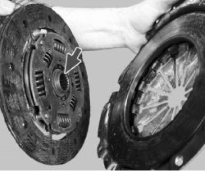
4. Cracks on the parts of the driven disk are not allowed. Check friction lining wear 1.
If the rivet heads 2 are recessed less than 0.2 mm, the surface of the friction linings is oily or the rivet connections are loose, then the driven disk must be replaced.
Check the reliability of fixation of the damper springs 3 in the sockets of the hub of the driven disk; if the springs are broken, the disk must be replaced.
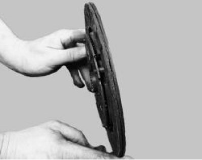
5. Check up beating of a conducted disk if during visual survey its warping is found out. If the runout is greater than 0.5 mm, replace the disc.
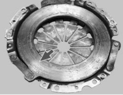
6. Inspect the friction surfaces of the flywheel and pressure plate, paying attention to the absence of deep scratches, scuffs, nicks, obvious signs of wear and overheating. Replace defective units.
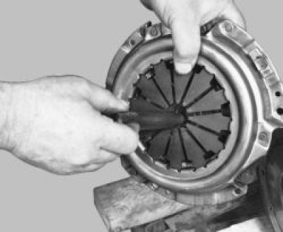
7. When loosening riveted connections 1 parts of the casing and the pressure plate, replace the casing with the pressure plate as an assembly. Visually evaluate the condition of the diaphragm spring 2 of the pressure plate. The presence of cracks on the diaphragm spring is not allowed. The points of contact of the spring petals with the clutch release bearing must be in the same plane and not have obvious signs of wear (wear should not exceed 0.8 mm). If not, replace pressure plate cover assembly.
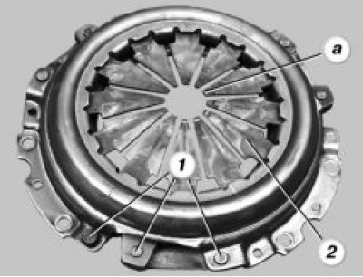
8. External survey estimate a condition of basic rings of a compression spring. Rings must be free of cracks and signs of wear. If not, replace pressure plate cover assembly.
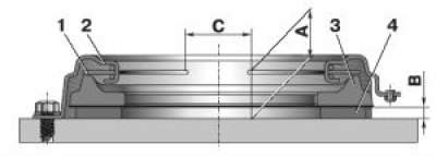
Checking the condition of the clutch drive disk: A, C - controlled dimensions; B is the distance between the intermediate ring 4 and the flywheel; 1 - pressure spring; 2 - casing; 3 - pressure plate; 4 - intermediate ring
To check the leading part of the clutch, fix the pressure plate 3 (pic. 5.5) assembled with a pressure spring 1 and a casing 2 on a fixture with an intermediate ring 4 with a thickness of B = (8,3±0,04) mm. This tool replaces the flywheel with driven disc.
Disengage the clutch three times with a disengagement stroke of 8–9 mm, applying a load to the pressure spring petals 1 at a diameter of C=34 mm. Do the following:
- check that the shutdown progress (8,0±0,1) mm corresponds to a pressure plate travel of at least 1.4 mm;
- the difference in values of the withdrawal of the pressure plate 3 is not more than 0.25 mm;
- size A should be within 29–31 mm;
- load on the petals of the pressure spring 1 on diameter C during the stroke (8,0±0,1) mm should be no more than 1100 N, peak shutdown load - no more than 1300 N.
9. Before installation of coupling check up ease of movement of a conducted disk on splines of a primary shaft of a transmission. If necessary, remove the causes of seizing or replace defective parts.
10. Pay attention to the fact that when installing the driven disk in the casing of the pressure plate, the more protruding part of the hub must be directed towards the pressure spring.
11. Insert the centering mandrel into the splines of the driven disc from the pressure spring side.
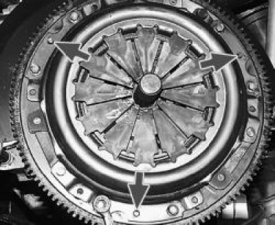
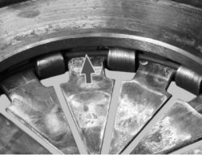
12. Install the clutch on the flywheel on the three centering pins (shown by arrows) and screw in the six clutch-to-flywheel bolts evenly in a criss-cross pattern, keeping the flywheel from turning. After that, remove the centering mandrel and install the gearbox.