




- key "13"
- screwdriver
- hammer
Remove the gearbox (see subsection 11.1.1.).
The reasons for incomplete clutch disengagement may be:
- warping of the driven and pressure plates;
- breakage of friction linings or loosening of driven disk rivets;
- jamming of the driven disk hub on the splines of the gearbox input shaft.
The reasons for incomplete clutch engagement may be:
- increased wear or oiling of the friction linings of the driven disk;
- oiling of the working surfaces of the flywheel and pressure plate.
Jerks during clutch operation can be caused by oiling of the friction linings of the driven disk, the working surfaces of the flywheel and pressure plate, or warping of the pressure plate.
A broken damper spring on the driven disc causes increased noise when the clutch is engaged.
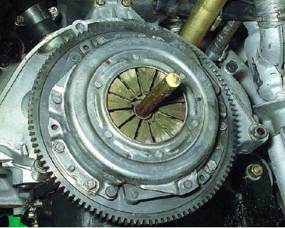
1. Install the mandrel into the pressure plate hole.
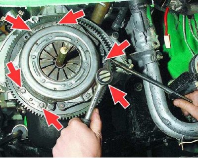
2. Use a screwdriver to prevent the flywheel from turning and unscrew the six bolts securing the clutch housing.
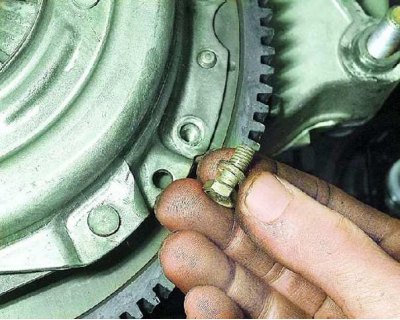
3. Please note: There is a spring washer under the head of each bolt.
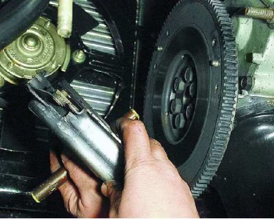
4. Remove the clutch housing assembly with the pressure and driven disks. Hold the driven disk while doing this, otherwise it may fall out.
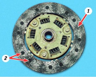
5. Cracks on the driven disk parts are not allowed. Check the condition and wear of the friction linings 1. If the rivet heads 2 are recessed less than 0.2 mm, the surface of the friction linings is oily or the rivet joints are loose, the driven disk must be replaced.

6. Check the reliability of the fixation of the damper springs in the sockets of the driven disk hub; if the springs are broken, the disk must be replaced.
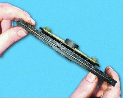
7. Check the runout of the driven disk if its warping is detected during visual inspection. If the runout exceeds 0.5 mm, replace the disk.
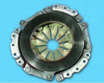
8. Inspect the working friction surfaces of the flywheel and pressure plate, paying attention to the possible appearance of deep scratches, nicks, dents, obvious signs of wear and overheating. Replace defective units.
9. Assess the condition of the casing parts and pressure plate by visual inspection; replace them as a whole if you find: loosening of the riveted connections of the casing parts...
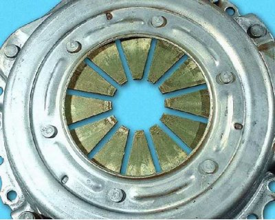
10....cracks on the diaphragm spring...
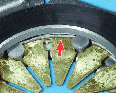
11....cracks and traces of wear on the support rings of the pressure spring...
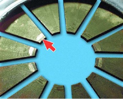
12....skewing of spring petals (the points of contact of the spring petals with the clutch release bearing must be in the same plane) and excessive wear at the points of contact with the bearing (wear should not exceed 0.8 mm).
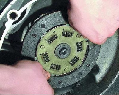
13. Before installing the clutch, check the ease of movement of the driven disk along the splines of the primary shaft of the gearbox. If necessary, eliminate the causes of jamming or replace defective parts.
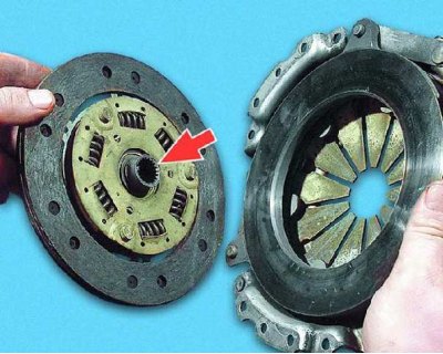
14. Please note that when installing the driven disk, the more protruding part of its hub should be directed towards the pressure spring.
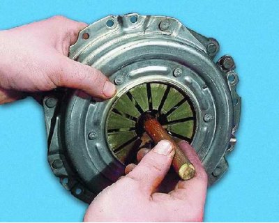
15. Insert the centering mandrel into the splines of the driven disk from the pressure spring side.
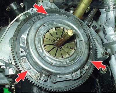
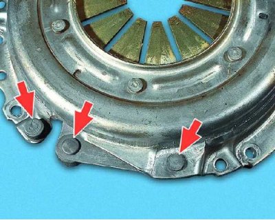
16. Install the clutch onto the flywheel using the three centering pins (shown by arrows) and tighten the six clutch-to-flywheel mounting bolts evenly in a crisscross pattern, holding the flywheel from turning. Remove the centering mandrel and install the gearbox.