
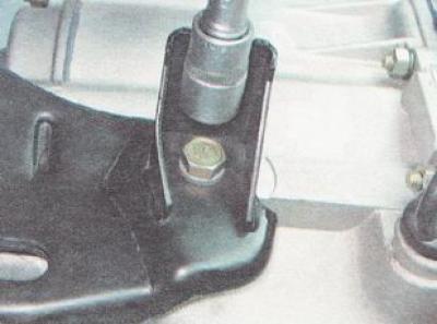
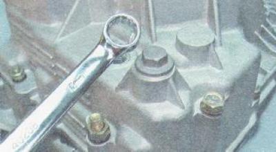
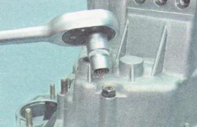
2. Using a 17 mm spanner, unscrew the two nuts securing the rear cover of the gearbox housing.
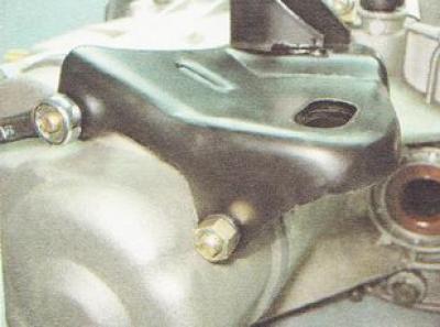
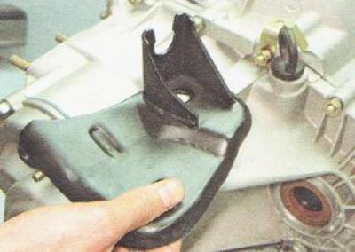
3. Remove the gearbox housing bracket.
4. Remove from the gearbox, the parts of the clutch release drive installed on it (see "Clutch release drive elements installed in the crankcase - removal and installation").
5. Remove the speed sensor from the gearbox (see "Vehicle speed sensor - check and replacement").
6. Remove the reversing light switch (see "The switch of lanterns of a backing - removal and installation").
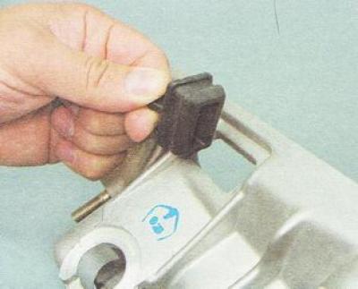
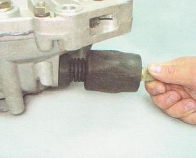
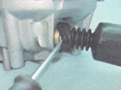
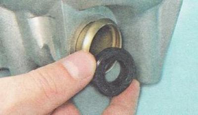
7. Remove the rubber plug from the clutch housing window.
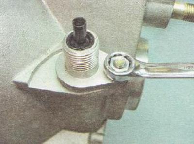
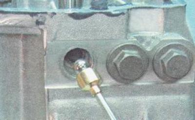
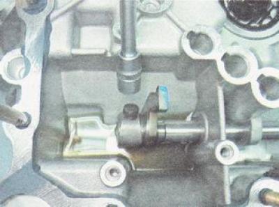
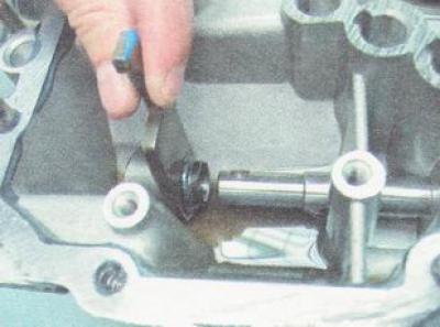
8. Using a 10 mm wrench, unscrew the nut securing the vehicle speed sensor drive.
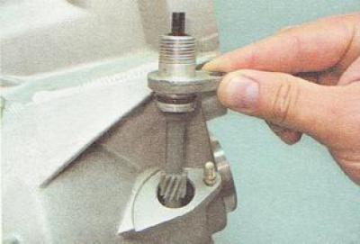
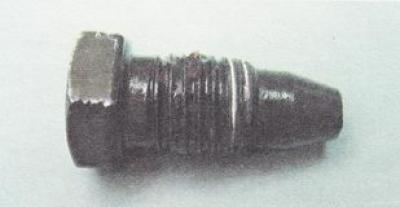
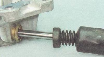
9. We remove the speed sensor drive from the hole in the gearbox housing.
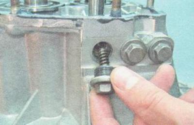
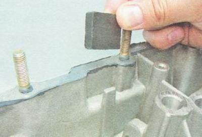
10. For ease of disassembly, unscrew the stud securing the gearbox housing to the engine cylinder block by turning it by two lock nuts, or with a stud driver.

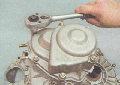
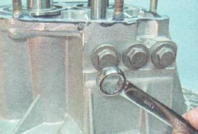
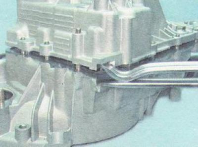
11. Using a 13 mm socket wrench with a deep head, unscrew the remaining four nuts securing the rear cover of the gearbox housing (two nuts were loosened when removing the powertrain support bracket).
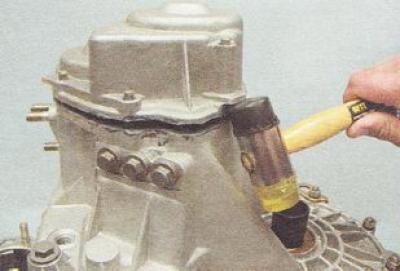
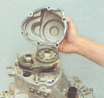
12. Lightly tapping on the tide of the cover with a rubber-faced hammer, or with an ordinary hammer through a wooden block, separate the cover from the gearbox housing.
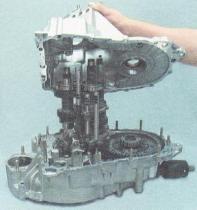
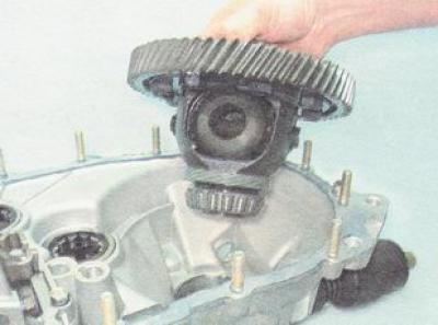
13. Remove the gearbox cover.
14. Without turning the hinge, we sink it, including the third gear.
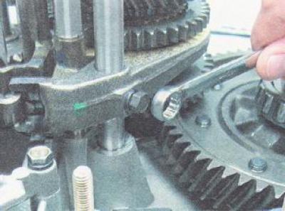
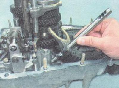
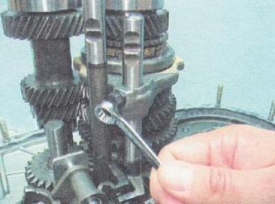
15. Using a 10 mm wrench, unscrew the bolt securing the fifth gear fork to the stem.
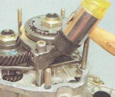
16. Lightly tapping the fork with a hammer with a rubber striker, we lower it down, including fifth gear.
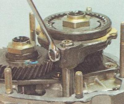
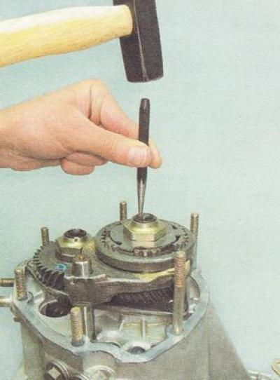
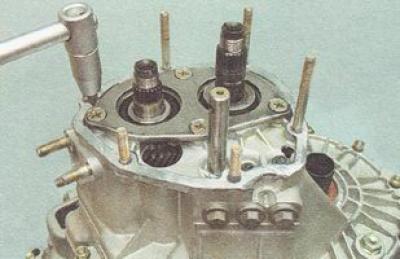
17. Using a center punch or a beard, we straighten the jammed edges of the nuts of the primary...
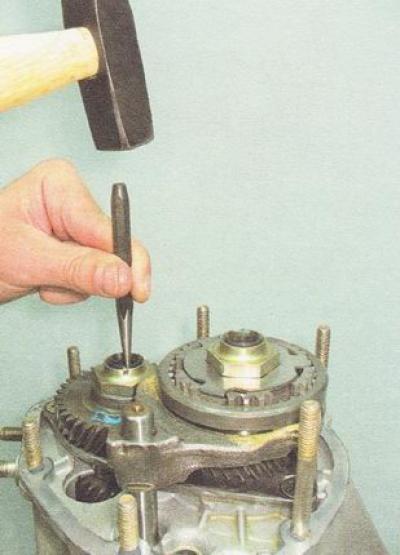
...and the secondary shaft of the gearbox.
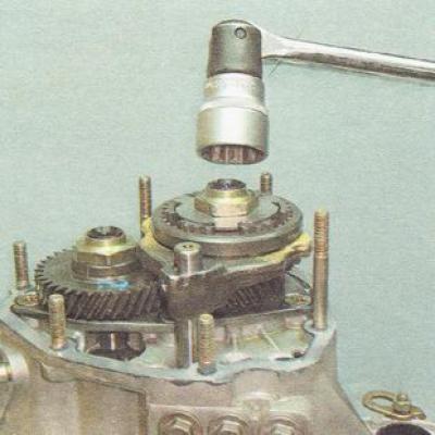
18. Using a 32 mm socket wrench with a long knob, unscrew the nuts of both shafts.
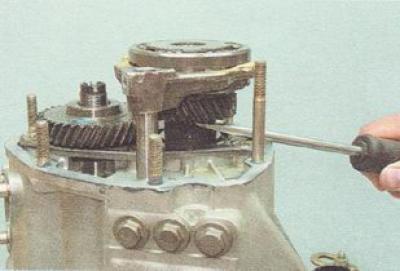
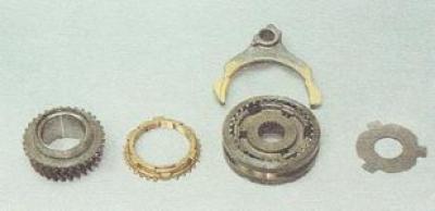
19. Prying with a screwdriver, remove the fifth gear from the secondary shaft along with the synchronizer blocking ring, clutch and fork.
20. We disassemble the node.
21. Remove the fifth gear bushing from the secondary shaft of the gearbox.
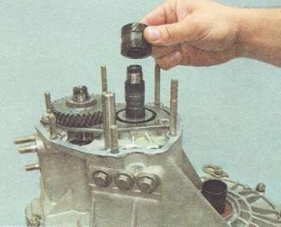
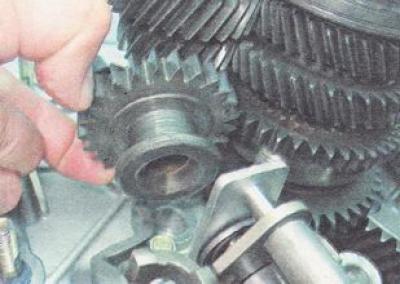
22. Prying off the gear with a screwdriver...
... remove the fifth gear drive gear from the input shaft of the gearbox.
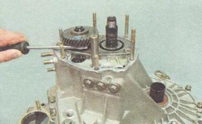
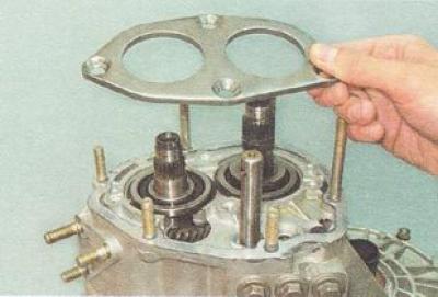
23. Using an impact screwdriver or a Phillips screwdriver, unscrew the four screws securing the thrust plate.
24. Remove the thrust plate.
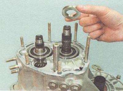
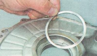
25. Remove the thrust washer from the secondary shaft of the gearbox.
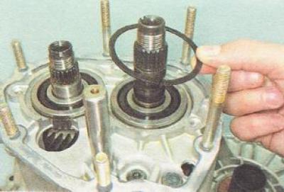
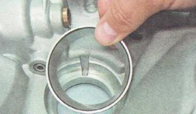
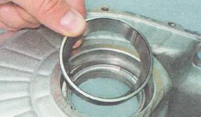
26. With expanding tongs, remove the circlips of the primary bearings...
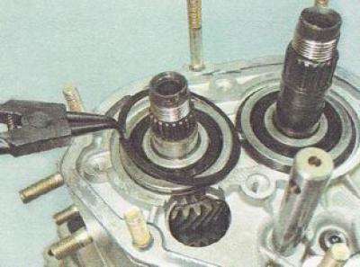
...and the secondary shaft of the gearbox.
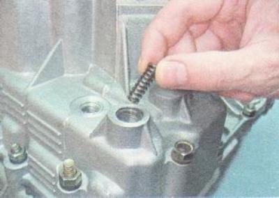
27. With a 13 mm key, unscrew the plug of the fifth gear rod retainer.
28. We take out the spring.
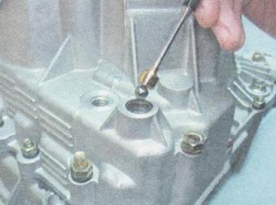
29. Using a magnet, we remove the retainer ball from the channel (you can also use a thin plastic tube, creating a vacuum in it with a rubber pear).
30. Similarly, remove the details of the clamps of the other two rods.
31. Using a 13 mm key, unscrew the plug of the reverse gear lock.
32. Remove the sealing washer of the stopper of the reverse gear lock.

33. We remove the spring from the hole...
...and a ball.
34. With a 13 mm socket wrench, unscrew 13 nuts...
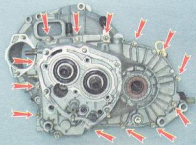
... and one bolt securing the gearbox housing to the clutch housing.
35. With two mounting blades, we disconnect the gearbox and clutch housings.
36. Remove the gearbox housing.
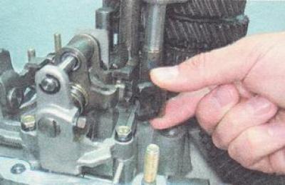
37. Using a 10 mm wrench, unscrew the bolt securing the first-second gear fork on the stem.
38. Remove the stem and fork of the first and second gears.
39. Using a 10 mm wrench, unscrew the bolt securing the third-fourth gear fork to the stem.
40. We remove the lever of the third-fourth gear fork rod from engagement with the gear selector lever.
41. Remove the third-fourth gear fork with the stem.
42. Remove the fifth gear fork rod.
43. We take out the axis of the reverse gear.
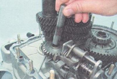
44. Having tilted, we remove the reverse gear from engagement with the gear selector lever and remove it.
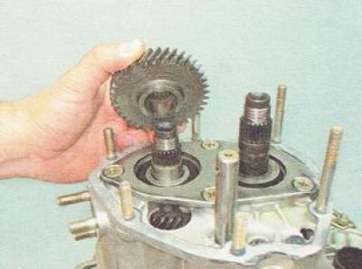
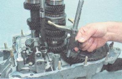
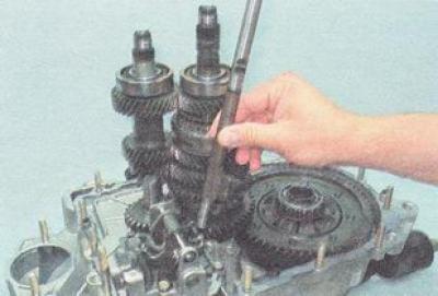
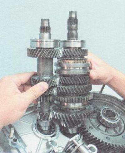
45. Simultaneously remove the primary and secondary shafts.
46. We take out the final drive gear with differential from the gearbox housing.
47. Using a 10 mm key, unscrew the three bolts securing the gear selection mechanism.
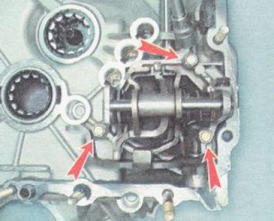
48. This bolt is longer than the others.
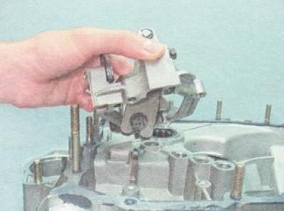
49. Remove the gear selection mechanism.
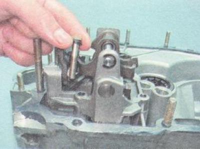
50. Using a 10 mm socket wrench, unscrew the bolt securing the gear selector rod lever.
51. A bolt with a conical tip is installed on the thread lock.
52. Remove the gear selector lever from the stem.
53. Prying with a screwdriver, remove the edge of the protective cover from the flanging.
54. We remove the rod of the gear selection mechanism from the gearbox housing.
55. In order not to lose the magnet when pressing out the bearings, we take it out of the seat.
56. We clean the magnet from metal particles.
Warning. If the gearbox bearings are in good condition, do not press their outer races out of the housings of the crankcases.
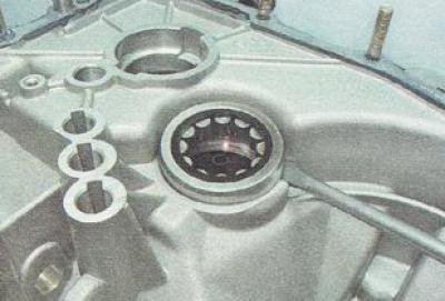
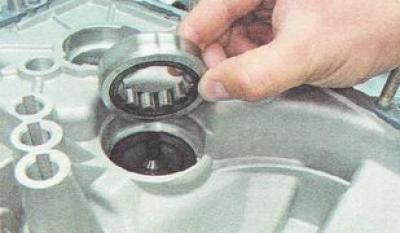
57. We abut the drift against the outer ring of the bearing in the area of the notch made in its seat. By applying light blows with a hammer on the drift, we press out...

... and remove the outer race of the input shaft roller bearing from the socket of the clutch housing.
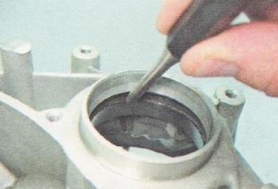
58. A special puller with a thin stop screw...
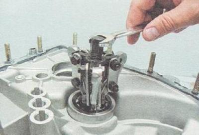
... or by prying it with a powerful screwdriver, we press it out...
... and remove the outer ring of the roller bearing of the output shaft from the socket of the clutch housing.
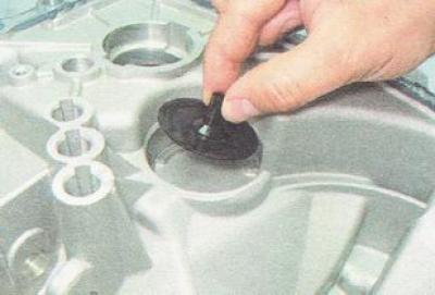
59. Remove the oil pan.
60. From the outside of the clutch housing with light hammer blows through the punch...
... we press out the outer ring of the differential bearing.
61. Similarly, we press out the second outer ring of the differential bearing from the gearbox housing.
62. An adjusting ring is installed under the outer ring of the differential bearing. When replacing the bearings of the differential or its housing in the gearbox, we change the adjusting ring to another one of the required thickness (see "Gearbox adjusting ring - selection of rings").
63. On the inside of the gearbox housing, rest a drift or slotted screwdriver against the outer edge of the stuffing box. Lightly tapping with a hammer on the tool...

... we press out the stem seal of the gear selection mechanism.
64. We wash the parts of the box in kerosene or diesel fuel, wipe them with a clean rag.
Gearbox check
We inspect the gearbox and clutch housings, the crankcase cover. They should not have cracks or chips. Holes for rods, sockets for bearings and seals should not have scoring, dents, wear marks. The outer races of the bearings must fit snugly into the seats with a slight interference.
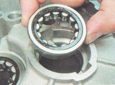
We look at the bearings. Roller bearings should rotate easily, without binding or noticeable play. On the working surfaces of the roller bearing rings, there should be no chipping and enveloping of metal, tint colors and wear marks (visible to the eye). Separators should not have cracks, deformations.
We inspect shafts, gears, clutches and synchronizer rings, gear shift rods and forks (to check the synchronizers, you will need to disassemble the output shaft, see below). On the teeth of gears and couplings there should be no chips, chipping of metal, signs of noticeable wear. Synchronizer rings and shift forks must be free of fatigue cracks. On the forks, slight wear of the working part is allowed. Rings with worn cone and teeth should be replaced even if the synchronizers in the box worked satisfactorily.
All defective parts must be replaced.