
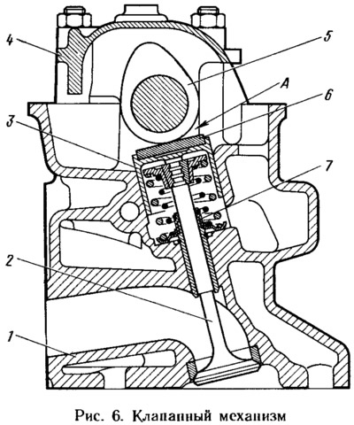
The valves are actuated directly by the camshaft cams through cylindrical pushers 3. In the pusher socket there is a washer 6, by selecting which the gap A in the gas distribution mechanism is adjusted.
Cylinder head
Cast aluminum with a wedge-shaped combustion chamber and press-fit cast iron seats and valve guides. The upper part of the bushings is sealed with rubber-metal oil-slinger caps 7. There are spiral grooves in the holes of the guide bushings to improve lubrication. The inlet valve bushings are grooved up to half the length of the hole, and the exhaust valve bushings are grooved along the entire length of the hole.
In the upper part of the cylinder head there are three bearings for the camshaft journals. The supports are detachable. The upper half is located in the bearing housing 4, and the lower half is in the cylinder head. The holes in the bearings are machined in assembly with the bearing housing, so it is not interchangeable and the head can only be replaced in assembly with the bearing housing.
Camshaft
Cast iron, cast, 3-support. On the rear side of the shaft there is an eccentric for driving the fuel pump. The working surfaces of the cams, the eccentric and the surface under the stuffing box are bleached to increase wear resistance.
Camshaft drive
Carried out by an elastic toothed belt 6 (pic. 7) from the toothed pulley 1 of the crankshaft. The same belt drives the pulley 2 of the coolant pump. Roller 3 serves to tension the belt. It rotates on an eccentric axle 7 attached to the cylinder head. By turning the axle relative to the fastening stud, you can change the belt tension.
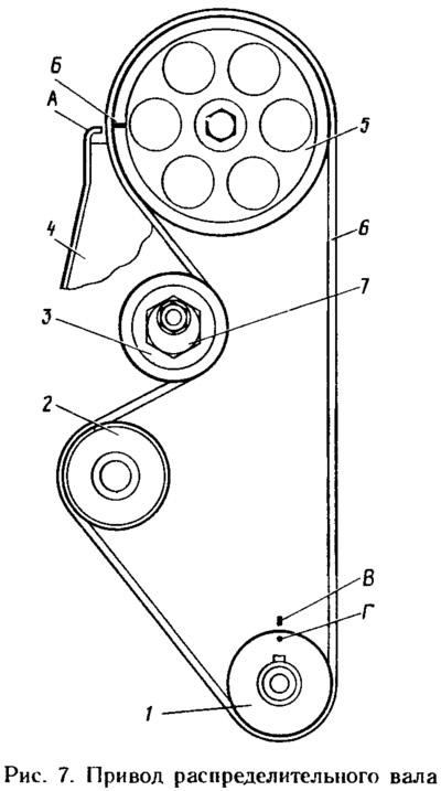
Since 1990, a belt with trapezoidal teeth has been used instead of a semi-circular toothed belt (with grooves on the tops of the teeth). Accordingly, the profile of the troughs on the toothed pulleys has also changed. The new belts are fully interchangeable with the old ones, i.e. a belt with trapezoidal teeth can be installed on pulleys with semicircular cavities and vice versa.
To check the correct relative position of the drive pulleys, there are alignment marks: B on the camshaft pulley 5 and the corresponding protrusion A on the back cover 4 of the belt; G on pulley 1 of the crankshaft and the corresponding mark B on the oil pump cover.