
The gas distribution mechanism is overhead valve, with a chain drive and an overhead camshaft. The overhead valve arrangement allows you to increase the compression ratio of the engine and improve the filling of its cylinders with a combustible mixture. The chain drive ensures silent operation of the mechanism.
Gas distribution mechanism (pic. 5) includes camshaft 14 with bearing housing 13, valve actuator levers 11, support adjusting bolts 18, valves 1 and 22, guide bushings 4 and valve springs 7 and 8 with fasteners.
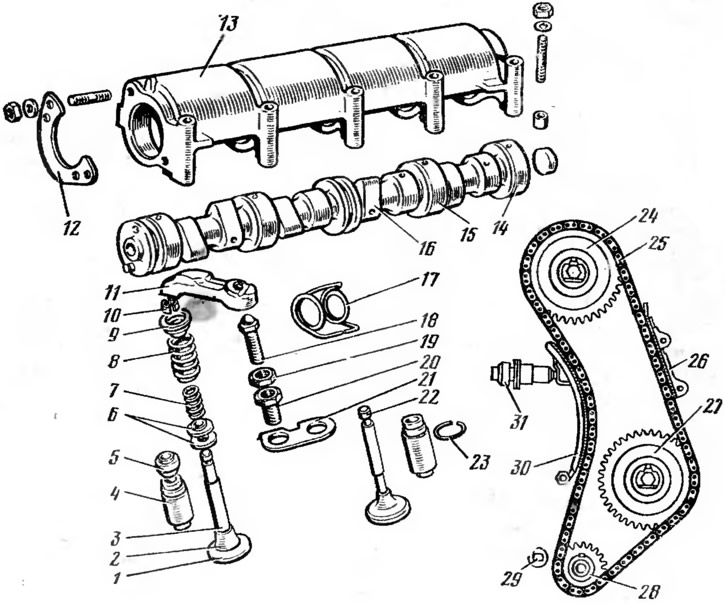
Pic. 5. Gas distribution mechanism of the engine:
1 - inlet valve; 2 - head; 3 - rod; 4 - guide sleeve; 6 - oil deflector cap; 6 - support washer; 7 - internal spring; 8 - outer spring; 9 - plate; 10 - cracker; 11 - valve drive lever; 12 - thrust flange; 13 - bearing housing; 14 - camshaft; 15 - support neck; 16 - cam; 17 - lever spring; 18 - adjusting bolt: 19 - nut; 20 - threaded bushing; 21 - locking plate; 22 - exhaust valve; 23 - retaining ring; 24 - camshaft sprocket; 25 - chain; 26 - chain damper; 27 - sprocket of the oil pump drive shaft; 28 - crankshaft sprocket; 29 - restrictive finger; 30 - shoe; 31 - tensioner.
Camshaft ensures timely opening and closing of valves. The camshaft is five-bearing, cast iron. It has 15 bearing journals and 16 cams (inlet and outlet). A channel passes through the shaft through which oil is supplied from the middle bearing journal to other journals and cams. A driven chain drive sprocket is attached to the front end of the shaft. The shaft is installed in a special bearing housing 13, which is fixed on the upper plane of the cylinder head 12 (see fig. 2). From axial movements, the camshaft is fixed by a thrust flange 12 (see fig. 5), which enters the groove of the front support journal and is attached to the end face of the bearing housing.
Camshaft drive is carried out through the driven sprocket 24 installed on it by a double-row roller chain 25 from the drive sprocket 28 of the crankshaft. This chain also rotates the sprocket 27 of the oil pump drive shaft. The chain tension is produced by the shoe 30, which is acted upon by the springs of the tensioner 31. To dampen the oscillations of the leading branch of the chain, there is a damper 26. The limiting pin 29 prevents the chain from falling off when the driven camshaft sprocket is removed on the car.
valves open and close the inlet and outlet channels. The valves are installed in the cylinder head in one row at an angle to the vertical axis of the engine cylinders. The inlet valve 1 has a larger diameter head than the outlet valve for better filling of the cylinders with the mixture. It is made of special steel. The outlet valve 22 operates under more severe temperature conditions than the inlet valve and is made of heat resistant steel.
Each valve consists of a head 2 and a stem 3. The head has a conical surface (chamfer), with which the valve, when closed, fits snugly against the seat installed in the cylinder head and also having a conical surface. The rod moves in a cast-iron guide sleeve 4, which is pressed into the cylinder head and ensures an accurate fit of the valve. An oil baffle cap 5 is put on the sleeve. The valve has two cylindrical springs: external 8 and internal 7. The springs ensure a tight fit of the valve in the seat and hold it in the closed position. The springs are mounted on the valve stem using a plate 9 and a split cracker 10. The valve is actuated from the camshaft cam lever 11, which rests at one end on the adjusting bolt 18, and the other on the valve stem. The adjusting bolt has a spherical head. It is screwed into a threaded sleeve 20 fixed in the cylinder head and fixed with a nut. Set the required clearance with the adjusting bolt (0.15 mm) between the camshaft cam and the valve lever on a cold engine. Spring 17 creates constant contact between the end of the actuator lever and the valve stem.