
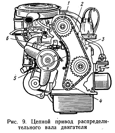
Timely provision of the engine with a combustible mixture and the release of cylinders from gases - these are the functions of the gas distribution mechanism. For all VAZ car models, except for VAZ-2105 and VAZ-2107, chain mechanism drive (pic. 9). In addition to chain 2, the drive includes: a steel drive sprocket 4 of the crankshaft, a driven sprocket 1 of the camshaft, a tensioner shoe 5 and a damper 3 of the chain.
To ensure the normal operation of the gas distribution mechanism during operation, regulate: the tension of the chain or drive belt; gaps between the cams and valve levers. The chain is tensioned to partially eliminate the noise it causes. We are speaking «partially», since it is impossible to completely eliminate noise, and reducing it due to excessive tension of the chain will only lead to its intensive wear.
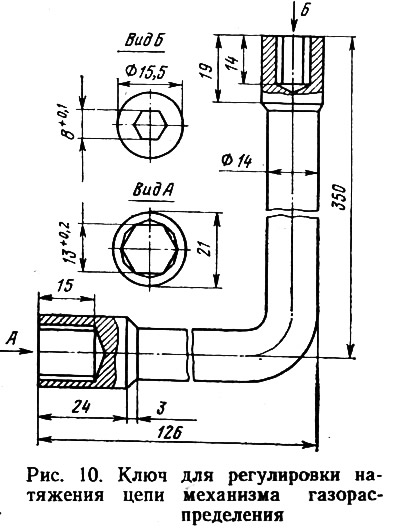
To tension the chain, you will need a crank and a wrench for the cap nut 6 of the tensioner. A few words about the wrench: the factory recommends using a 13mm wrench. In practice, it has been found that this is not the most convenient key for this operation. Unscrewing the cap nut is greatly simplified if you follow the example of some Moscow service stations and make a special key (pic. 10). By the way, it is successfully used when removing the cylinder head cover and adjusting the door locks.
The process of adjusting the chain tension must be performed in the following order: with a special key (or a key with a size of 13 mm) loosen cap nut 6 of tensioner 5; crank the crankshaft 1-1.5 turns.
The tensioner springs, acting on the shoe, will automatically set the correct chain tension. Then tighten the cap nut 6. After completing the operation, pull out the starting handle. It is expedient to carry out this operation at the removed cover of a head of cylinders. In this case, the chain tension can be checked by pressing with a finger with a force of 49.04 N between the sprocket and chain guide 3. The chain should bend 4-5 mm.
Sometimes on a hot engine after adjustment, an extraneous clattering sound appears. This tensioner rod touches the bottom of the cap nut 6. Unscrew the nut with the engine off, remove the collet clamp and ring, place a washer 0.2-0.3 mm thick and 16 mm in diameter under the clamp. The mechanism assembled with an additional washer will not knock. If you do not provide the necessary tension, the chain will make increased noise. Not only that, she can break the pacifier. It happens that a poorly stretched chain acquires a special «agility» and jumps over the teeth of the camshaft gear. As a result, a «failure» in the valve timing, and the engine fails to work.
You have to get used to the rustling noise of the gas distribution mechanism. At first, it disturbs, it seems criminal, but it is the specific noise of a chain drive. However, it should not increase. An increase in noise is a signal for action.
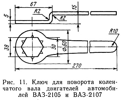
On VAZ-2105 and VAZ-2107 cars, the belt tension operation is also simple. Remove the protective cover and loosen the bolts securing the turntable 10 (see fig. 7) tension roller 11. When turning the crankshaft [to simplify the operation, it is advisable to make a key (pic. eleven)] for two or three turns, the spring 3 will tension the belt 5 without anyone's help. It remains to tighten the bolts and install the cover.
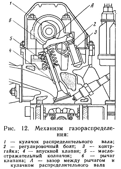
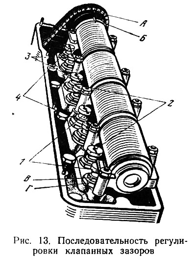
A chain with a tensioner is just a drive for the gas distribution mechanism itself (pic. 12), which performs the functions of a combustible mixture distributor. In order for the process of fuel injection and gas exhaust to proceed normally, there must be some clearance A between lever 6 and cam 1. This condition is necessary, since the valves operate at high temperatures and, naturally, increase in size. It is these gaps that are subjected to verification and adjustment. If the gap is large, i.e. more than 0.15 mm, the valve starts to knock. It is not difficult to determine this knock, since its frequency is less than any other knock (the valves are driven by the camshaft, and it rotates 2 times slower than the crankshaft). There may not be a knock, but adjustment is needed anyway. This happens when the valve «clamped», i.e. the gap is less than 0.15 mm.
As you can see, the valves require normal clearances, otherwise the compression drops, the valves burn, deform, the engine does not develop power, loses throttle response, runs unstably and overheats.
It is not difficult to learn how to independently adjust the valves, only attention, accuracy and skill are needed. When performing the operation, the following are required: a special key with a size of 17X17 mm, the peculiarity of which is that the key head is located at an angle of 45°and this eliminates the possibility of damage to the breaker-distributor when adjusting the clearances of the first and second valves; tubular wrench size 8 mm (or a special key shown in fig. 10); screwdriver; pliers, key size 17 mm; a device for measuring the angle of rotation of the slider, made from an old breaker cover. Remove the cover of the breaker-distributor without pulling the wires out of it, and instead of the cover, install a device for measuring the angle of rotation of the slider. The contacts on the inside of the device, located at 90°, serve as marks, opposite which it is necessary to stop the rotor plate when turning the crankshaft.
Clearance adjustment must be carried out on a cold engine (at a temperature not higher than 20°С). While the engine is cooling, you can dismantle everything that will interfere with the operation. So that nothing superfluous gets into the carburetor, it is advisable to close the carburetor inlet necks with a sheet of paper or cardboard, putting it on the studs. When removing the cylinder head cover, do not apply much force, but rather, lift it with one hand, push it slightly forward with the other along the vehicle.
You can start adjusting the clearances only by specifying in which of the cylinders the piston is at top dead center. If using the crank or key (see fig. eleven) for VAZ-2105 and VAZ-2107 cars, turn the crankshaft to a position where marks A to B (pic. 13) are aligned, then at that moment the piston of cylinder IV will reach top dead center. You have to start with him. You can adjust using probes with a thickness of 0.14 and 0.16 mm or using special devices manufactured by the domestic industry.
At present, thanks to the ingenuity of individual motorists, several methods for adjusting valve clearances have become widespread and recognized by specialists. Traditional probes are beginning to give way to indicators, special rulers, etc. The industry has already mastered the production of new devices for these purposes («Reference», URZ-01, etc.), however, the adjustment sequence remains the same regardless of the method and measuring instruments.
So, the gaps of the exhaust valve of cylinder IV and the intake valve of cylinder III are the first to be adjusted (see fig. 13 pos. 1). While holding the head of the adjusting bolt B with one wrench, with the other (crooked) loosen the lock nut D. A 0.14 mm feeler gauge should enter and exit between the lever and the cam. Screwing and unscrewing the adjusting bolt B, achieve the required clearance. If you are satisfied with the adjustment made, fix the position of the adjusting bolt by tightening the locknut. After that, be sure to recheck the gap.
To move on to the valves of the next cylinder, the crankshaft must be rotated 180°. A device for measuring the angle of rotation of the slider will come to the rescue here. Facilitate this operation for VAZ-2105 and VAZ-2107 car engines (fix the exact angle of rotation of the crankshaft) it is possible, using the advice of a motorist from Donetsk, who suggested marking the camshaft pulley, starting from the factory mark, every 10.5 teeth. Given that the number of teeth on the pulley is 42, this marking greatly simplifies the installation of the crankshaft during the adjustment process.
Many motorists prefer to use the most modern methods of adjusting clearances and successfully master the devices (pic. 14). Experience, however, shows that when adjusted using an indicator, the readings of the latter are not always stable. Reason: possibility of leverage (rocker) move in the longitudinal direction. A number of proposals have been put forward on how to eliminate the influence of the unstable position of the lever. One of them is as follows: after installing the tool, loosen the lock nut 3 (see fig. 12), if necessary, eliminate the skew growls, unscrew the adjusting bolt 2 until it stops the levers and cam 1; loosen the bolt until a guaranteed clearance of 0.01-0.02 mm appears; set the indicator scale to 0; tighten the adjusting bolt until the indicator shows a value of 0.5 minus the guaranteed clearance of 0.01-0.02 mm; in this position, tighten the lock nut 3.
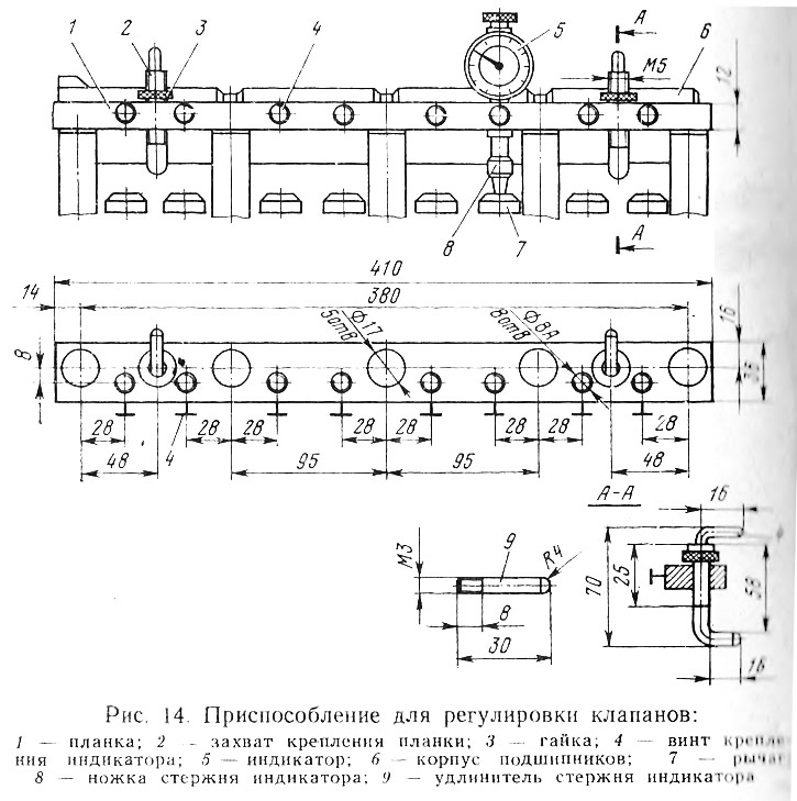
It should be remembered that the Volga Automobile Plant managed to somewhat change the shape of the lever, and therefore motorists will experience certain difficulties when adjusting the gaps on the first and eighth valves. It is possible to facilitate adjustment if in the fixture bar (pic. 14) drill a hole with a diameter of 17 mm to a diameter of 18.5 mm and slightly bend the indicator leg.
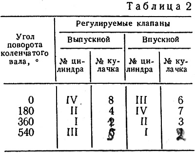
The second will adjust the clearances of the exhaust valve of cylinder II and the intake valve of cylinder IV (see fig. 13 pos. 2), then after the next rotation of the crankshaft, the clearances of the exhaust valve of cylinder I and the intake valve of cylinder II (pos. 3). The operation will be completed by adjusting the clearance of the exhaust valve of cylinder III and intake cylinder I (pos. 4). In order not to be mistaken, you can use the valve adjustment sequence diagram when turning the crankshaft (tab. 2).
After completing the adjustment, all removed parts must be reinstalled.
Particular attention should be paid to the cylinder head cover gasket. If the gasket has dents, cracks or tears, then it makes no sense to install it, since oil leakage from under such a gasket is inevitable. The new gasket should be carefully placed in place and, when installing the cover on it, make sure that the gasket does not protrude from under the flanging. The gasket is rubber.
If it is evenly pressed on all sides, it will provide reliable tightness. The uniformity of efforts during tightening can only be ensured by a torque wrench. The Rigaselmash plant has mastered the production of these keys. Purchase the DK-25 key.
Remember that performing such operations as tightening the block head, installing the camshaft bearing housing, etc., is simply impossible without a torque wrench.
When returning the parts to their place, pay attention to the condition of the various nozzles, tubes and hoses put on them. All of them should not have burrs, torn edges and folds.
You can not ignore the air filter. It should be remembered that the air filter element does not last forever. It performs important rough work and over time becomes clogged with dust and dirt. A dirty filter starts to do more harm than good. It is not only unable to clean the intake air, but also does not provide the carburetor with the right amount of air. The intensity of pollution depends on the operating conditions. If, when driving on asphalt, the filter element serves 10-15 thousand km, then on dusty dirt roads it clogs faster. Inspect the filter and replace it with a new one if necessary.
If there are no air filters available for sale, and their condition is unsatisfactory, proceed as follows: remove the contaminated filter material from the plastic frame and replace it with a material of the type «sipron», which is widely used in various filters.
There are red and blue marks on the air filter housing cover. They have a certain meaning. These marks and the embossed arrow on the housing serve to seasonally adjust the air filter. A blue mark means summer, in which case fresh outside air enters the filter. With a red mark, which means winter time, air preheated by the exhaust manifold enters the filter. After replacing the filter element, position the cover so that the mark corresponding to the season is opposite the arrow.
Before reinstalling the parts dismantled from the engine when adjusting the valves, it makes sense to carry out another very important operation: tighten the cylinder head mount. The plant advises to carry out this operation twice: after 2 and after 5 thousand kilometers. It is during the first thousand kilometers that as a result of repeated changes in temperature, the tightness of the fit of the head, made of aluminum alloy, to the cast-iron block is violated. The iron-asbestos spacer installed between them is somewhat crumpled, so this three-layer composition requires a screed.
What does the weakening of the density between the head of the block and the block itself lead to? The tightness of the cooling and lubrication system is broken, Antifreeze leaks, it enters the engine crankcase, the oil loses its daily qualities, etc. Tightening the cylinder head fastening should be performed on a cooled engine and, most importantly, always with a torque wrench.
The head is fastened with ten main and one additional bolts, and they must be tightened according to a certain pattern and in two steps, given in the car's operating instructions. All ten main bolts are tightened to 112.8 Nm. Bolt A (see «Operating Instructions») tighten with a torque of 37.3 Nm.
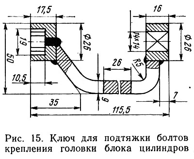
If possible, make the key shown in fig. 15, and when tightening the block head, it will not be necessary to remove the camshaft bearing housing.
After finishing work with the gas distribution mechanism, take care of the ignition distributor-breaker.