
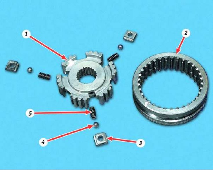
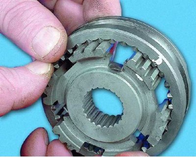
Synchronizer details: 1 - hub; 2 - clutch; 3 - cracker; 4 - ball; 5 - spring
If the gear is switched on fuzzy or with great effort, or does not turn on at all, before disassembling the output shaft, check the operation of the synchronizer: the synchronizer clutch must be moved manually with little effort. If the clutch is difficult to move (does not move or moves with great force), repair the synchronizer or replace it as an assembly. Spontaneous disengagement of gears indicates wear or damage to the teeth of the synchronizer clutch and gear rims.
1. Before disassembly, mark the position of the coupling relative to the hub.
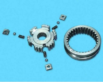
2. Carefully disassemble the synchronizer by removing the clutch from the hub. At the same time, make sure that the spring-loaded crackers with balls do not scatter in different directions.
3. Examine the details of the synchronizer. Chips and nicks on the splines of the hub and coupling are unacceptable (especially pay attention to the ends of the teeth of the coupling), damage or signs of seizing on crackers, balls and springs. Replace defective parts or synchronizer assembly.
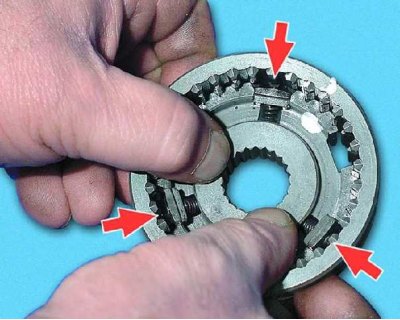
4. Install the coupling on the hub in accordance with the previously made marks. Wherein...
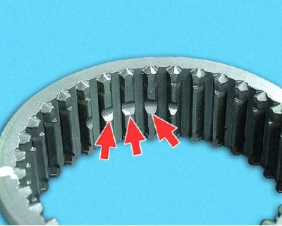
5....three large grooves on the splines of the coupling must match...
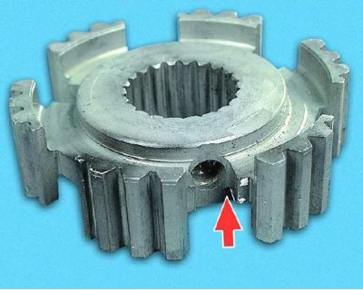
6....with hub slots for retainers (with holes).
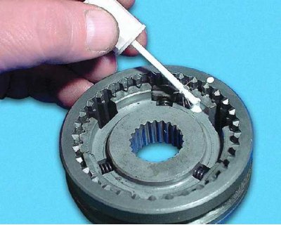
7. Lubricate the retainer spring with Litol-24 grease and insert it into the hole in the hub groove.
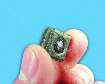
8. Lubricate the cracker with Litol-24 grease and insert a ball into its hole.
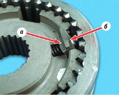
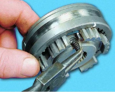
9. While compressing the spring, insert the cracker with the ball into the groove of the hub. The grooves a on the cracker should be outward, and the spherical (big) surface b must face the coupling.
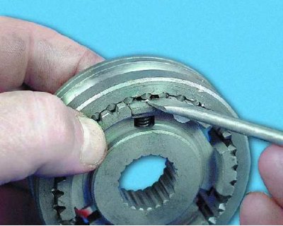
10. Push the cracker so that the ball falls into the grooves on the splines of the coupling.
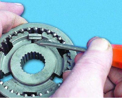
11. Adjust the spring with a screwdriver so that it gets into the cracker hole. Install the rest of the fasteners in the same way.