

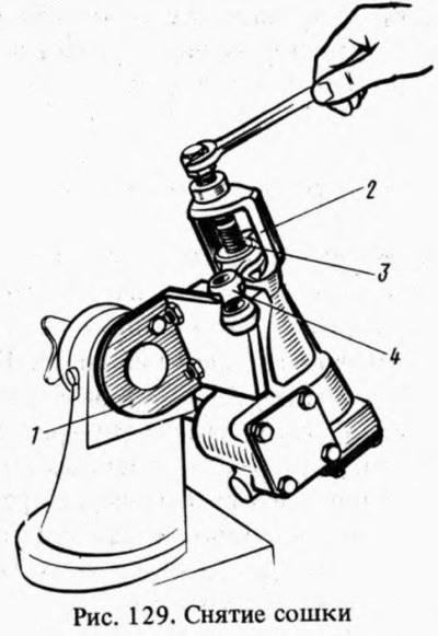
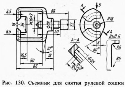
Having unscrewed the nut of fastening of the steering eye 4 (pic. 129) and, having removed the spring washer, with a puller A.47043 (pic. 130) remove the bipod. Having unscrewed the fastening bolts, remove the cover 5 (see fig. 125) together with the adjusting screw 2, the adjusting plate 1, the lock washer and the lock nut 3. The shaft 11 of the bipod assembly with the roller 12 is removed from the crankcase 7.
Having unscrewed the fastening bolts, they remove the cover 17 of the thrust bearing of the worm shaft together with the shims 16. With the shaft 13 of the worm, the outer ring of the bearing 15 is pushed out of the crankcase and the shaft is removed along with the bearing separators. Remove the gland 18 of the worm shaft and the gland 9 of the bipod shaft.
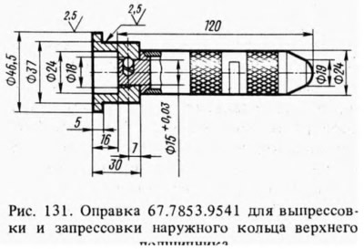
Mandrel 67.7853.9541 (pic. 131) press out the outer ring of the upper bearing. At the same time, the removable nozzle on the handle of the mandrel is placed with the shoulder back.
Assembly is carried out on bracket A.74076/R in the reverse order of disassembly, taking into account the following:
- the outer ring of the upper bearing of the worm is pressed in with mandrel 67.7853.9541, rearranging the nozzle on the handle of the mandrel with the reverse side;
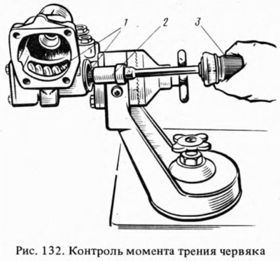
- after installing worm 1 (pic. 132) into the crankcase of the steering mechanism and fixing the bottom cover is checked using a dynamometer 02.7812.9501 (5) and heads А.95697/5 (2) moment of friction of the worm shaft; it should be within 2-5 kgf cm. If the friction moment is less than the specified, reduce the thickness of the shims, and if more - increase;
- having installed the bipod shaft, make sure that there is no gap in the engagement of the roller with the worm in the positions of the worm shaft turned to the right and left by 30°from the neutral position of the bipod. A possible gap is eliminated with an adjusting screw 2 (see fig. 125) and tighten locknut 3;
- after adjusting the gap in the engagement of the roller and the worm, the worm friction moment is checked with a dynamometer, which should be equal to 9-12 kgf cm when the worm shaft is rotated 30°both to the left and to the right from the middle position and decrease smoothly to 7 kgf cm when turning from an angle of 30°to the stop.
Upon completion of the assembly, the angles of rotation of the bipod from the neutral position are checked, which should be 32°10'±1°both to the left and to the right until the bipod stops against the bolt heads, then 0.215 l of oil is poured into the crankcase.