




Contents: Testing the generator on the bench ↓ Checking the rotor excitation winding ↓ Stator check ↓ Checking the rectifier block valves ↓ Checking additional diodes of…↓ Checking the voltage regulator ↓ Checking the capacitor ↓
Testing the generator on the bench
Allows you to determine the generator's serviceability and whether its characteristics correspond to the nominal ones. The brushes of the generator being tested must be well ground to the contact rings, and the rings themselves must be clean.
Install the generator on the stand and make connections as shown in Fig. 228. For generator 37.3701, a 12 V, 3 W lamp is switched on between terminals "30" and "61". Switch on the stand's electric motor, set the generator output voltage to 13 V with rheostat 4 and bring the rotor speed to 5000 min⁻¹. Let the generator run in this mode for at least 2 minutes, and then measure the output current. For a serviceable generator, it should be at least 45 A (55 A for generator 37.3701).
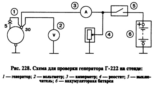
If the measured value of the output current is less, this indicates faults in the stator or rotor windings, damage to the valves or wear of the contact rings and brushes. In this case, a thorough check of the windings and valves is necessary to determine the location of the fault.
The generator output voltage is checked at a rotor speed of 5000 min⁻¹. Using a rheostat, set the output current to 15 A and measure the generator output voltage, which should be (14.1±0.5) V at an ambient air and generator temperature of (25±10)°C.
If the voltage does not fit within the specified limits, then replace the voltage regulator with a new one, known to be in good working order, and repeat the test. If the voltage is normal, then the old voltage regulator is damaged. And if the voltage still does not fit within the above limits, then it is necessary to check the windings and valves of the generator.
Checking the rotor excitation winding
The excitation winding can be checked without removing the generator from the car, by removing only the voltage regulator together with the brush holder. If necessary, clean the contact rings with sandpaper, use an ohmmeter or test lamp to check whether there is a break in the excitation winding and whether it shorts to the housing.
Stator check
The stator is checked separately after disassembling the generator. The terminals of its winding must be disconnected from the rectifier valves. First of all, check with an ohmmeter or with a test lamp and a battery whether there are breaks in the stator winding and whether its turns are shorted to the housing.
The insulation of the winding wires must be free of overheating, which occurs when there is a short circuit in the rectifier valves. Replace the stator with such a damaged winding. Then check with a special defectoscope whether there are short-circuited turns in the stator winding.
Checking the rectifier block valves
There are three positive and three negative valves in the rectifier block. The positive valves are pressed into the plate of the rectifier block, connected to the "30" terminal of the generator. The negative valves have a minus of the rectified current on the housing and are pressed into another plate of the rectifier block, connected to the housing.
A working valve allows current to flow in only one direction, while a faulty valve may not allow current to flow at all (chain break) or pass current in both directions (short circuit). If one of the rectifier valves is damaged, replace the entire rectifier unit.
A short circuit of the valves can be checked without removing the generator from the car, after disconnecting the wires from the battery and the generator. You can check with an ohmmeter or with a lamp (1-3 W) and a battery, as shown in Fig. 229.
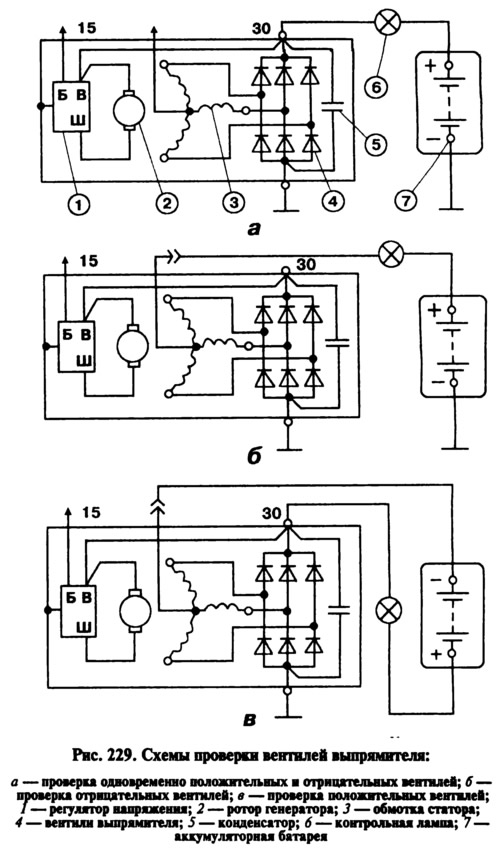
First check if there is a short circuit in both the positive and negative valves. To do this, connect the "+" of the battery through the lamp to the "30" terminal of the generator, and the "-" of the battery to the generator body (fig. 229, a). If the lamp is on, then both the negative and positive valves are shorted.
You can check for a short circuit of the negative valves by connecting the "+" of the battery through a lamp to the plug of the neutral wire of the stator winding, and the "-" of the battery to the generator housing (fig. 229, b). The lamp burning means a short circuit in one or more negative valves. It should be remembered that in this case the lamp burning may be a consequence of the stator winding turns shorting to the generator housing. However, such a malfunction occurs much less frequently than a short circuit of the valves.
To check for a short circuit in the positive valves, connect the "+" battery via a lamp to the "30" terminal of the generator, and the "-" battery to the stator winding zero point terminal plug (fig. 229, in). Lighting of the lamp will indicate a short circuit of one or more positive valves.
Generator 37.3701 does not have a separate plug for outputting the zero point. But the screws for fastening the rectifier unit are connected to it. Therefore, when checking the valves of generator 37.3701, connect the wires from the test lamp or battery to the heads of these screws. In addition, before checking, disconnect the terminal "B" of the voltage regulator from terminal "30" of the generator and the wire from the terminal "B" of the voltage regulator.
A break in the valves without disassembling the generator can be detected only indirectly when checking the generator on a bench by a significant decrease (by 20-30%) in the strength of the output current compared to the nominal. If the generator windings are in good condition and there is no short circuit in the valves, then the reason for the decrease in the output current is a break in the valves.
Checking additional diodes of generator 37.3701
A short circuit of additional diodes can be checked without removing and disassembling the generator. Just as for checking the rectifier block valves, it is necessary to disconnect the wires from the battery and generator and the wire from the "B" terminal of the voltage regulator.
connect the battery "plus" through a lamp (1-3 W, 12 V) to the generator terminal "61", and "-" to one of the rectifier unit mounting screws. If the lamp lights up, then there is a short circuit in one of the additional diodes. The damaged diode can only be found by removing the rectifier unit and checking each diode separately.
A break in the additional diodes can be detected with an oscilloscope by the distortion of the voltage curve on the "61" plug, as well as by the low voltage (below 14 V) on the "61" plug at the average rotation frequency of the generator rotor.
Checking the voltage regulator
The regulator operates by continuously and automatically changing the excitation current of the generator so that the generator voltage is maintained within specified limits when the rotor speed and generator load current change.
Check on the carto check, you need a DC voltmeter with a scale of up to 15-30 V, accuracy class of at least 1.0.
After 15 minutes of engine operation at medium speeds with the headlights on, measure the voltage between terminal "30" and the generator housing. The voltage should be within 13.6-14.6 V.
If the battery is systematically undercharged or overcharged and the regulated voltage does not fall within the limits specified above, replace the voltage regulator.
Checking the removed regulator. Check the voltage regulator removed from the generator according to the diagram shown in Fig. 230. It is better to check the generator regulator 37.3701 assembled with the brush holder, since in this case you can immediately detect breaks in the brush terminals and poor contact between the terminals of the voltage regulator and the brush holder.
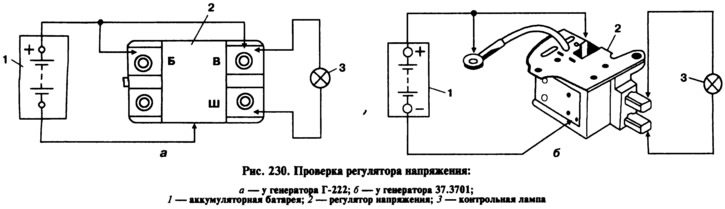
Between pins "W" and "B" of the controller (or between the brushes on the generator 37.3701) turn on a 1-3 W, 12 V lamp. Connect a 12 V power source to terminals "B" and "C" and to the regulator body, and then a 15-16 V power source. If the regulator is working properly, the lamp should light in the first case, but not in the second.
If the lamp lights up in both cases, then there is a breakdown in the regulator, and if it does not light up in both cases, then either there is a break in the regulator or there is no contact between the brushes and the terminals of the voltage regulator (on generator 37.3701).
Checking the capacitor
The capacitor serves to protect the electronic equipment of the car from voltage pulses in the ignition system, as well as to reduce interference with radio reception. Damage to the capacitor or weakening of its fastening on the generator (deterioration of contact with the body) it is detected by an increase in interference to radio reception when the engine is running.
The capacitor's serviceability can be approximately checked with a megohmmeter or tester (on a scale of 1-10 MOhm). If there is no break in the capacitor, then when the device probes are connected to the capacitor terminals, the arrow should move toward decreasing resistance, and then gradually return back. The capacitor's capacity is 2.2 μF±20%.