
Checking the generator on the stand
Testing on the bench allows you to determine the health of the generator and the compliance of its characteristics with the nominal ones. For the generator under test, the brushes must be well ground to the slip rings of the collector, and the rings themselves must be clean.
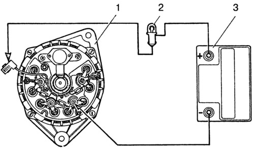
Install the generator on the stand and make the connections as shown in fig. 9-7. Turn on the electric motor of the stand, set the generator output voltage to 13 V with rheostat 4 and bring the rotor speed to 6000 min-1. Let the generator run in this mode for at least 10 minutes, and then measure the recoil current. For a working generator, it should be at least 80 A.
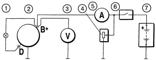
Pic. 9-7. Connection diagram for testing the generator on the stand:
1 - control lamp 12 V, 3 W; 2 - generator; 3 - voltmeter; 4 - rheostat; 5 - ammeter; 6 - switch; 7 - battery.
If the measured value of the recoil current is much less, then this indicates a malfunction in the stator and rotor windings or damage to the valves. In this case, a thorough check of the windings and valves is necessary to determine the location of the fault .
The voltage at the generator output is checked at a rotor speed of 5000 min-1. Using rheostat 4, set the output current to 15 A and measure the voltage at the generator output, which should be 13.2-14.7 V at ambient and generator temperature (25±10) °C.
If the voltage is not within the specified limits, replace the brush holder with voltage regulator with a new, known-good one, and retest. If the voltage is normal, then the old voltage regulator is damaged and must be replaced. And if the voltage still does not fit within the above limits, then it is necessary to check the windings and generator valves.
Checking the generator with an electronic oscilloscope
The oscilloscope allows you to accurately and quickly check the health of the generator and determine the nature of the damage by the shape of the rectified voltage curve.
To check, assemble the circuit according to Fig. 9-8. Disconnect the common terminal wire of the three additional diodes from the plug «D+» voltage regulator and take care that the tip of the disconnected wire does not short-circuit with «weight» generator. To plug «D+» regulator, connect the wire from the battery through switch 1. Thus, the excitation winding will be powered only from the battery.
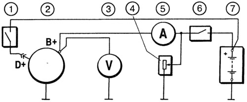
Pic. 9-8. Connection diagram for checking the generator with an oscilloscope:
1 - switch; 2 - generator; 3 - voltmeter; 4 - rheostat; 5 - ammeter; 6 - switch; 7 - battery.
Turn on the electric motor of the stand and bring the rotor speed up to 1500-2000 min-1. Use switch 6 to disconnect the battery from the terminal «B+» generator and rheostat 4, set the output current to 10 A.
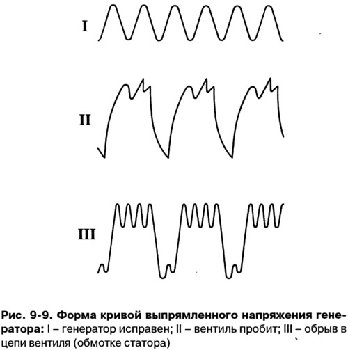
Use an oscilloscope to check the voltage at the terminal «B+» generator. With serviceable valves and stator winding, the rectified voltage curve has a sawtooth shape with uniform teeth (pic. 9-9, I). If there is an open in the stator winding or an open or short circuit in the valves of the rectifier unit, the shape of the curve changes dramatically: the uniformity of the teeth is disturbed and deep cavities appear (pic. 9-9, II and III).
By checking the shape of the voltage curve at the terminal «B+» generator and making sure that it has a normal appearance, check the voltage on the plug «D» generator with the wire disconnected from the plug «D+» voltage regulator. Plug «D» is a common output of three additional diodes that feed the excitation winding when the generator is running. The shape of the voltage curve here should also have a regular sawtooth shape. An irregular shape of the curve indicates damage to the additional diodes.
Checking the excitation winding of the rotor
The excitation winding can be checked without removing the generator from the car, removing only the protective cover and voltage regulator together with the brush holder. Having cleaned, if necessary, with a sandpaper, the slip rings, an ohmmeter or a test lamp, check whether there is an open in the excitation winding and whether it closes with «weight».
Stator check
The stator is checked separately, after removing the rectifier unit.
First of all, check with an ohmmeter or with the help of a test lamp and a battery, whether there are any breaks in the stator winding and whether its turns are closed on «mass».
The insulation of the winding wires must be free from overheating, which occurs during a short circuit in the valves of the rectifier unit. Replace a stator with such a damaged winding.
Finally, after disassembling the generator, it is necessary to check with a special flaw detector whether there are short-circuited turns in the stator winding.
Checking the rectifier valves
A good valve only allows current to flow in one direction. Faulty - may either not pass current at all (open circuit), or pass current in both directions (short circuit).
If one of the rectifier valves is damaged, the entire rectifier unit must be replaced.
A short circuit in the rectifier unit valves can be checked without removing the generator from the vehicle, by first disconnecting the wires from the battery and the generator and removing the cover from the rear cover of the generator. Also disconnect the wire from the output «D+» voltage regulator. You can check with an ohmmeter or with a lamp (1-5W, 12V) and battery as shown in Fig. 9-10.
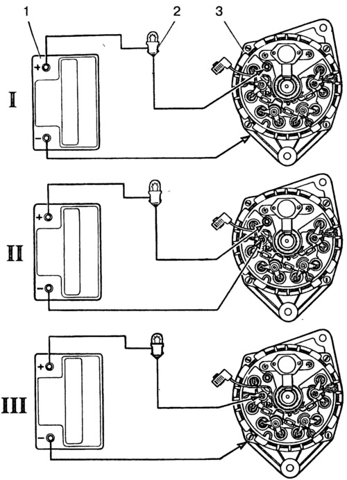
Pic. 9-10. Schemes for checking rectifier valves:
1 - battery; 2 - control lamp; 3 - generator; I - check at the same time «positive» and «negative» valves; II - check «positive» valves; III - check «negative» valves.
Note. In order to simplify the fastening of parts of the rectifier, three valves (with red mark) create on the body «plus» rectifier block. These valves «positive», and they are pressed into one plate of the rectifier unit, connected to the output «B+» generator. Other three gates («negative» with black mark) have on the body «minus» rectifier block. They are pressed into another plate of the rectifier unit connected to «weight».
First check if there is a short circuit at the same time in «positive» and «negative» valves. For this «plus» connect the batteries through the lamp to the terminal «B+» generator, and «minus» to the generator housing (pic. 9-10, I). If the lamp is on, then «negative» and «positive» valves are short circuited.
To check for a short circuit in «positive» valves «plus» connect the batteries through the lamp to the terminal «B+» generator, and «minus» - with one of the phase terminals of the stator winding (pic. 9-10, II). Burning lamp will indicate a short circuit of one or more «positive» valves.
Short circuit «negative» valves can be checked by connecting «plus» batteries through a lamp with one of the phase terminals of the stator winding, and «minus» with generator housing (pic. 9-10, III). Burning lamp means a short circuit in one or more «negative» valves. It should be remembered that in this case, the burning of the lamp may also be the result of a short circuit of the turns of the stator winding on the generator housing. However, such a malfunction is much less common than a short circuit of the valves.
An open in the valves without disassembling the generator can be detected either with an oscilloscope or when checking the generator on the stand for a significant reduction (by 20-30%) the magnitude of the recoil current compared to the nominal. If the windings, additional diodes and the generator voltage regulator are in good order, and there is no short circuit in the valves, then the reason for the decrease in the output current is an open in the valves.
Checking additional diodes
A short circuit of additional diodes can be checked without removing and disassembling the generator according to the circuit shown in fig. 9-11. As well as for checking the valves of the rectifier unit, it is necessary to disconnect the wires from the battery and the generator, remove the protective cover of the generator and disconnect the wire from the output «D+» voltage regulator.
Pic. 9-11. Scheme for testing additional diodes:
1 - generator; 2 - control lamp; 3 - battery.
«Plus» batteries through the lamp (1-3W, 12V) attach to output «D» generator, and «minus» - to one of the phase terminals of the stator winding.
If the lamp lights up, then there is a short circuit in one of the additional diodes. You can find a damaged diode only by removing the rectifier unit and checking each diode individually.
An open in additional diodes can be detected with an oscilloscope by distorting the voltage curve on the plug «D», as well as low voltage (below 14 V) on plug «D» at an average frequency of rotation of the generator rotor.
Checking the voltage regulator
The operation of the voltage regulator is to continuously and automatically change the generator excitation current in such a way that the generator voltage is maintained within the specified limits when the generator speed and load current change.
Vehicle check. To check, you must have a DC voltmeter with a scale of up to 15-30 V with an accuracy class of at least 1.0.
After 15 minutes of engine operation at medium speed with the headlights on, measure the voltage between the terminal «B+» and «weight» generator. The voltage should be in the range of 13.2-14.7 V.
In the event that a systematic under-charging or overcharging of the battery is observed and the regulated voltage does not fit within the specified limits, the voltage regulator must be replaced.
Checking the removed regulator. The regulator assembly with the brush holder, removed from the generator, is checked according to the diagram shown in fig. 9-12.
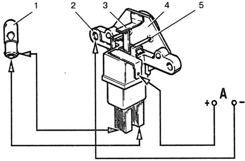
Pic. 9-12. Scheme for testing the voltage regulator:
1 - control lamp; 2 - conclusion «weight» voltage regulator; 3 - output «DF» voltage regulator; 4 - voltage regulator; 5 - output «D+» voltage regulator; A - to the power source.
Between the brushes, turn on the lamp 1-3 W, 12 V. To the conclusions «D+» and «weight» regulator, connect the power supply first with a voltage of 12 V, and then with a voltage of 15-16 V.
If the regulator is working, then in the first case the lamp should be on, and in the second it should go out.
If the lamp is on in both cases, then there is a breakdown in the regulator, and if it does not light in both cases, then either there is an open in the regulator, or there is no contact between the brushes and the outputs of the voltage regulator. The latter can be checked by connecting the wires from the lamp not to the brushes, but directly to the terminals «D+» and «DF» voltage regulator.
Capacitor check
The capacitor is used to protect the electronic equipment of the car and reduce radio interference.
Capacitor damaged or loose on alternator (poor contact with «weight») detected by an increase in radio interference when the engine is running.
Approximately the health of the capacitor can be checked with a megaohmmeter or tester (on a scale of 1-10 MΩ). If there is no break in the capacitor, then at the moment the probes of the device are connected to the terminals of the capacitor, the arrow should deviate in the direction of decreasing resistance, and then gradually return back.
Capacitor capacitance, measured with a special device, should be 2.2 uF±20%.