




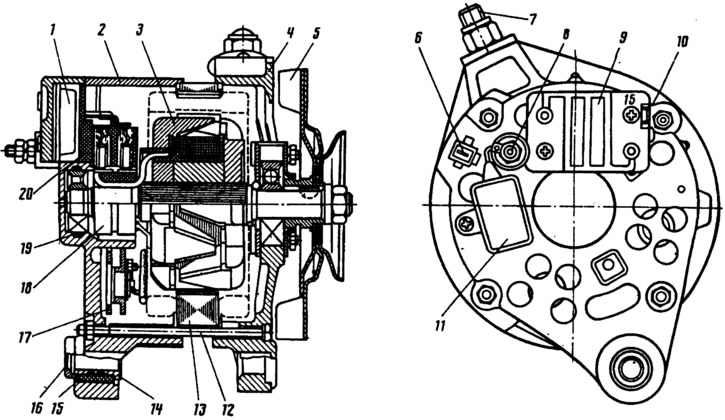
Fig. 226. Generator G-222:
1 - voltage regulator; 2 - cover from the contact ring side; 3 - rotor; 4 - drive side cover; 5 - pulley with fan; 6 - neutral wire plug; 7 - generator mounting stud to tension bar; 8 - output "30" of the generator; 9 - voltage regulator housing; 10 - terminal "15" of the generator (terminal "B" of the voltage regulator); 11 - capacitor; 12 - tension bolt; 13 - stator; 14 - bushing; 15 - buffer bushing; 16 - pressure sleeve; 17 - rectifier block; 18 - slip rings; 19 - rubber ring; 20 - brush holder.
The rotor consists of a shaft onto which a steel bushing and two steel beak-shaped poles are pressed, forming a magnetic system. On the steel bushing between the beak-shaped poles in a plastic frame is the rotor winding, called the excitation winding. Its ends are connected to contact rings 18, installed on a plastic block pressed onto the rotor shaft. Current is supplied to the excitation winding through brushes pressed by springs to the contact rings.
Stator 13 is assembled from electrical steel plates connected by electric welding. Three phase windings connected in a star with plug 6 of the neutral wire are placed in the internal slots of the stator. Until 1985, the relay of the control lamp of the accumulator battery charge was connected to it. The alternating voltage induced in the stator winding is converted into direct voltage by rectifier unit 17, assembled on six silicon valves of the VA-20 type according to a three-phase bridge circuit. Microelectronic voltage regulator 1 is combined in one unit with brush holder 20.
Fig. 227 shows the generator connection diagram, which has a charge control lamp, used before 1985. Since 1985, relay 3, control lamp 7 and the corresponding wires are not installed, since one voltmeter 6 is quite sufficient to monitor the generator voltage.
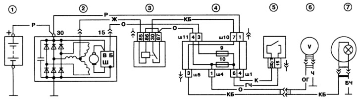
Fig. 227. Wiring diagram of the G-222 generator on a VAZ-2105 vehicle:
1 - battery; 2 - generator; 3 - Battery charge indicator lamp relay; 4 - mounting block; 5 - ignition switch; 6 - voltmeter; 7 - battery charge indicator lamp located in the instrument cluster.
Since 1988, some vehicles may be equipped with a 37.3701 type generator. It differs from the G-222 generator mainly in the rotor and stator windings, voltage regulator, and the introduction of three additional diodes in the rectifier block to supply the excitation winding and to operate the charge indicator lamp.