
Disassembly
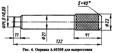
The connecting rod and piston group is removed and installed during disassembly and assembly of the engine removed from the car. The disassembly of the connecting rod and piston group begins with the removal of the piston rings. Then the piston is placed in a support with a cylindrical recess and with the help of a mandrel (pic. 4) type A.60308, centered in the hole of the piston pin, the pin is pressed out under a press (with a force of at least 800 kgf). The use of a hammer for pressing-pressing is unacceptable: the piston may be damaged.
If some parts of the connecting rod and piston group are not damaged and slightly worn, then they can be reused. Therefore, when disassembling, they mark them in order to later assemble a group with the same parts and install them in the same engine cylinder.
Assembly
Pre-selected, as indicated below, the parts are assembled in the following order. The connecting rod is placed in an electric furnace and kept there at a temperature of 240°C for at least 15 minutes. The finger is put on roller 1 in advance (pic. 5) fixtures 02.7853.9500 for engine 2105 or A.60325 for engines 2103 and 2101. Guide 2 is installed at the end of the roller and fixed with screw 3. The screw is loosely tightened so that jamming does not occur when the finger expands from contact with the heated connecting rod.
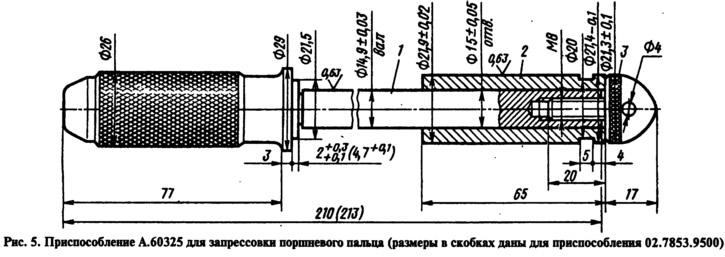
The connecting rod removed from the furnace is quickly clamped in a vice and the piston is put on the connecting rod so that the P mark on the piston is on the side of the oil hole on the lower head of the connecting rod. The piston pin fixed on the tool is pushed into the piston hole and the upper head of the connecting rod until the edge of the tool handle stops against the piston. During this operation, the piston should be pressed against the upper head of the connecting rod in the direction of pressing the pin. This will place the finger in the correct position.
The pin should be pressed in as soon as possible, since the connecting rod cools quickly, and in a cooled connecting rod it is impossible to change the position of the pin. After cooling the connecting rod, lubricate the finger with engine oil through the holes in the piston bosses.
Lubricate the grooves on the piston and piston rings with engine oil. Install the rings on the piston, orienting them so that the lock of the upper compression ring is located at an angle of approximately 45°to the axis of the piston pin, the lock of the lower compression ring is at an angle of approximately 180°to the axis of the lock of the upper compression ring, and the oil scraper ring lock is at an angle of approximately 90°to the lock axis of the upper compression ring.
The lower compression ring is installed downwards with a groove that it has on the outer surface. If the ring is marked «Top» or «TOR», then the ring is installed with the mark up. For oil scraper rings manufactured before 1987, the chamfers on the outer surface were asymmetrical. Therefore, these rings must be installed on the piston with chamfers up. Before installing oil scraper rings, it is checked that the joint of the spring expander is located on the side opposite to the ring lock.