
Disassembly
Remove piston rings. The piston is placed in a support with a cylindrical recess and, using the mandrel A.60308 *, centered in the hole of the piston pin, the pin is pressed out under pressure (force not less than 0.8 tf). The use of a hammer for pressing-pressing is unacceptable: the piston may be damaged.
* Stepped mandrel with a diameter and length of the working part, respectively, 21 and 80 mm. Centering shank diameter (14,9±0,05) mm.
If some parts of the connecting rod and piston group are not damaged and slightly worn, then they can be reused. Therefore, when disassembling, they mark them in order to later assemble a group with the same parts and install them in the same engine cylinder.
Assembly
Before assembly, pick up a finger to the piston. For proper mating, it is necessary that the piston pin, lubricated with engine oil, enter the piston bore by simply pressing the thumb and not fall out of it if you hold the piston with the piston pin in a vertical position. The drop-down finger is replaced by another, of the following category (see «Device Features» in the same chapter). If the piston had a third category pin, then replace the piston with a piston pin.
Since the pin is inserted into the upper head of the connecting rod with an interference fit, it is necessary to heat it up to expand the upper head. To do this, the connecting rods are placed for 15 minutes in an electric furnace heated to 240°C.
The finger is prepared in advance for assembly by putting it on roller 1 (pic. 36) accessories A.60325 (used for older cars) and installing between the fingers and the handle a distance ring 4 mm thick, with an outer diameter of 22 mm and an inner diameter of 15 mm. A guide 2 is installed at the end of the device and fixed with a screw 3. The screw is loosely tightened so that jamming does not occur when the finger expands from contact with the heated connecting rod.
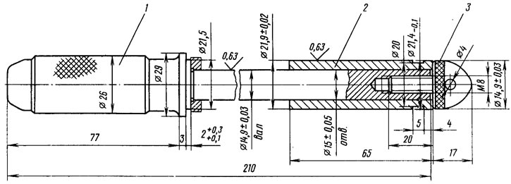
Pic. 36. Device A.60325 for pressing the piston pin
To properly connect the pin to the connecting rod, press-fitting must be carried out as soon as possible, since the connecting rod cools quickly and after cooling it will not be possible to change the position of the pin. The piston with connecting rod must be assembled so that the arrow on the piston crown points towards the outlet of the oil hole on the bottom head of the connecting rod (see fig. 4).
The connecting rod removed from the furnace is quickly clamped in a vice. Put the piston on the connecting rod, making sure that the hole for the finger coincides with the hole in the upper head of the connecting rod. The piston pin fixed on the fixture is pushed into the piston bore and into the upper head of the connecting rod (pic. 37) until the stop of the shoulder of the tool in the piston. During this operation, the piston must be pressed by the boss against the upper head of the connecting rod in the direction of pressing the pin (shown by the arrow in Fig. 37). Then the finger will take the correct position.
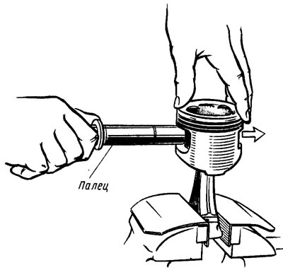
Pic. 37. Pressing the piston pin into the upper head of the connecting rod
After cooling the connecting rod, lubricate the finger with engine oil through the holes in the piston bosses. Install the piston rings, placing their locks through 120°. The lower compression ring is installed with the groove down.