
2. In an oven already heated to 240°C, the connecting rods are placed for 15 minutes.
3. To properly connect the pin to the connecting rod, press the pin in as soon as possible, as the connecting rod cools quickly and after cooling it will not be possible to change the position of the pin.
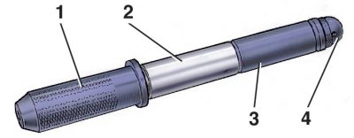
4. Prepare finger 2 for assembly in advance by putting it on roller 1 of fixture A.60325, installing guide 3 at the end of this roller and fixing it with screw 4. Tighten the screw loosely so that jamming does not occur when the finger expands from contact with the heated connecting rod.
5. Quickly clamp the connecting rod removed from the oven in a vise. Place the piston on the connecting rod, making sure that the hole for the pin coincides with the hole in the upper head of the connecting rod.
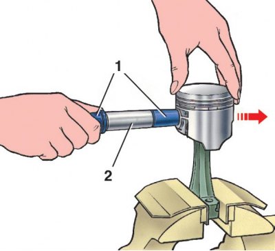
6. Using tool A.60325, push the fixed piston pin 2 into the piston hole and into the upper head of the connecting rod so that the shoulder of the tool comes into contact with the piston (1 - adaptation A.60325). During this operation, the piston must be pressed by the boss against the upper head of the connecting rod in the direction of pressing the pin (shown by arrow). Thus, the finger will take the correct position.
Attention! If there is an oil outlet hole on the lower head of the connecting rod, then the piston must be connected to the connecting rod so that the mark «P» on the piston and the hole on the connecting rod were on the same side.
7. After the connecting rod has cooled, lubricate the pin with engine oil through the holes in the piston bosses.
8. When installing piston rings, position their locks through 120°. Install the rings so that the recess on the outer surface of the second (scraper) the compression ring was facing down and the chamfers on the outer surface of the oil scraper ring were facing up (see fig. The main dimensions of the piston, connecting rod, piston pin and piston rings).
9. The connecting rod is machined with the cap, so the caps are not interchangeable. In order not to confuse them during assembly, the number of the cylinder in which they are installed is stamped on the connecting rod and the corresponding cover. When assembling, the numbers on the connecting rod and cap must be on the same side.