
Timing chain tension adjustment
Chain tension adjustment is carried out in the following order. Loosen cap nut 1 (see fig. 17) tensioner. Turn the crankshaft 1-1.5 turns in the direction of rotation. In this case, the tensioner springs will automatically set the correct chain tension. After that, tighten the cap nut of the tensioner.
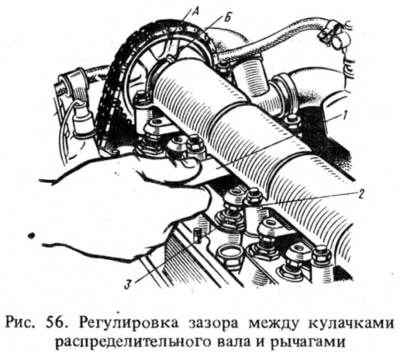
Adjustment of the gap between the levers and camshaft cams. Gap adjustment must be done very carefully. The gap is adjusted on a cold engine, after adjusting the chain tension. After adjustment, the gap should be 0.14-0.17 mm. Adjustment is carried out after tensioning the chain in the following order:
- turn the crankshaft clockwise until mark A matches (pic. 56) on the camshaft sprocket with the mark B on the bearing housing, which corresponds to the end of the compression stroke in the 4th cylinder. In this position, adjust the clearance at the exhaust valve of the 4th cylinder (8th cam) and inlet valve of the 3rd cylinder (6th cam);
- holding the lever adjusting bolt 2 with a wrench, with another wrench;
- loosen the lock nut 3, insert a flat feeler gauge A.95111 between the lever and the camshaft cam (7) 0.15 mm thick and 30 mm wide and tighten the bolt, followed by tightening the lock nut until the probe enters with a slight pinch when the lock nut is tightened;
- sequentially turn the crankshaft 180°, adjust the clearances at the intake valve of the 4th and exhaust valve of the 2nd cylinders, then at the intake valve of the 2nd and exhaust valve of the 1st cylinder, finally at the intake valve of the 1st and exhaust valve 3 th cylinder.
Pump Drive Belt Tension Adjustment
Under normal belt tension, its deflection under a force of 10 kgf between the generator and pump pulleys should be within 10–15 mm or 12–17 mm between the pump and crankshaft pulleys. To increase the tension, loosen the nuts securing the generator, move it away from the engine and tighten the nuts.
Setting the ignition timing
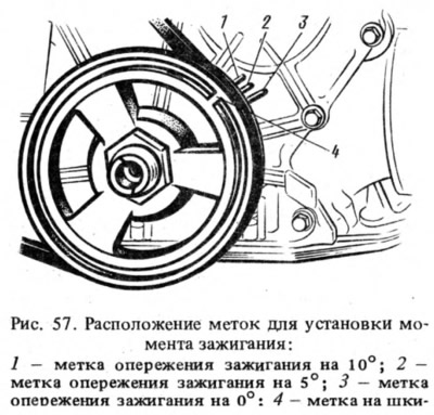
To check the ignition timing, there are three marks 1, 2, 3 (pic. 57) on the cover of the timing mechanism drive and mark 4 on the crankshaft pulley, corresponding to the TDC of the piston in the 1st and 4th cylinders.
It is convenient to check and set the ignition timing using a stroboscope. Wherein:
- install an octane corrector eccentric (if it exists) ignition distributor to the zero position;
- connect clamp "+" stroboscope with clip "+B" ignition coils, and ground clamp (corps) - with clamp " battery;
- insert an adapter for connecting a strobe lamp between the spark plug wire of the 1st cylinder and the spark plug, mark mark 4 on the crankshaft pulley with chalk for greater visibility and start the engine, directing the flashing stroboscope light stream to the mark on the pulley, which, when the ignition timing is correctly set at idle engine should be against mark 2 on the cover of the timing mechanism drive.
If the marks do not match, then stop the engine, loosen the nut and set it to the desired angle. To increase the ignition timing, the distributor housing should be turned counterclockwise, and to decrease it, clockwise. Then check the ignition timing again.
If there is a diagnostic stand with an oscilloscope, then it can also be used to easily check the ignition timing setting, proceeding as described in the instructions for the stand.
Carburetor Drive Adjustment
With the pedal fully depressed 9 (see fig. 36) the throttle valve of the primary chamber must be fully open and its lever must not have additional travel. When the pedal is released, the damper should be fully closed. Adjustment is made by changing the length of the rod 2 by rotating its tip. At the same time, the length of the rod 1 is checked and, if necessary, adjusted, for which the center-to-center distance of the tips should be 80 mm.
The air damper control drive is adjusted by changing the fastening of the cable and sheath so that when the handle is fully extended 6 (see fig. 36) the air damper was completely closed, and with the recessed handle, it was completely open.
Engine idle adjustment
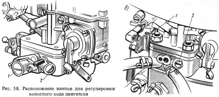
The elements that regulate the idle speed of the engine include screw 2 (pic. 58), which determines the composition of the mixture (screw'' quality"), and screw 1 of the mixture amount (for carburetors 2101-1107010, 2101-1107010-02 and 2101-1107010-03, when screw 1 is tightened, the throttle valve opens slightly).
To exclude violation of the factory adjustment of the carburetor, a restrictive sleeve is pressed onto screw 2 (for carburetors 2105-1107010-20 and 2105-1107010-10, restrictive bushings are pressed onto both screws). Blue bushings are installed at the factory, red bushings at service stations. If the bushings fail to adjust the carbon monoxide content (SO) in the exhaust gases, it is necessary, by unscrewing the screws, to break the heads of the bushings, unscrew the screws, remove the bushings from them and screw the screws back into their original place.
Idle speed adjustment is carried out on a warm engine (coolant temperature 90-95°C and oil temperature 75-85°C) with adjusted gaps in the gas distribution mechanism and with a correctly set ignition timing.
For carburetors 2105-1107010-20 and 2105-1107010-10 screw 1 (pic. 58, a) the amount of the mixture on the tachometer of the stand, the crankshaft speed is set in the range of 820-900 rpm, then the mixture composition screw 2 achieves a CO concentration in the exhaust gases within 0.5-1.2% at this position of the screw 1.
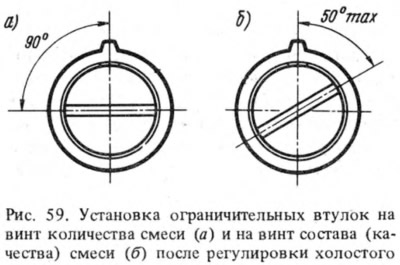
Screw 1 restores the rotational speed within 820-900 rpm. If necessary, restore the CO concentration with screw 2 to 0.5-1.2% and press restrictive bushings onto the screws, orienting the slots of the bushings relative to the protrusions, as shown in Fig. 59.
For carburetors 2101-1107010-03 screw 1 (pic. 58b) set the speed of the crankshaft in the range of 720-800 rpm using the tachometer of the stand. Then, screw 2 achieves a CO concentration in the exhaust gases of 1.5-2.5% at a given throttle position.
Screw 1 restore the crankshaft speed to 720-800 rpm. If necessary, use screw 2 to restore the CO concentration to 1.2–2.5% and press a restrictive sleeve onto it, as shown in Fig. 59.6.
The engine idle speed adjustment can be carried out even in the absence of a gas analyzer. But at the same time, after adjustment, the content of carbon monoxide in the exhaust gases is not guaranteed when the engine is idling.
When adjusting the amount of the mixture with screw 1, the minimum stable crankshaft speed is set, then with screw 2 of the mixture quality, the engine is operated at the maximum crankshaft speed at a given screw position.
With screw 1, the crankshaft speed is reduced to the minimum stable operation of the engine, and then screw 2 is screwed in until the engine runs with noticeable interruptions. Then turn the screw 30-60° (no more) until stable engine operation is achieved.
Check the correctness of the adjustment by sharply pressing the accelerator and releasing it. The engine must not be stopped.