Removal and installation
See section «Disassembly and assembly of the rear axle». After installation, check the operation of the axle shafts in road conditions.
Checking the technical condition
Parts included in the axle shaft kit must meet the following requirements:
- the bearing must not be damaged or worn; if the axial clearance in it exceeds 0.7 mm, replace it;
- the retaining ring and bearing must not be offset from the original fit;
- if the inner ring of the bearing rotates relative to the seat belt of the axle shaft, replace the locking ring;
- the axle shaft must not be deformed, and the seating surfaces must not have scratches or damage. The runout of the axle shaft, measured in the centers on the neck under the stuffing box, should not exceed 0.08 mm.
Before installation in the centers, the centering holes on the axle shaft must be thoroughly cleaned of dirt and rust. Eliminate slight bending of the axle shaft by editing on the press. After straightening the rod, the runout of the flange end, measured in the centers, should not exceed 0.05 mm. If the runout of the flange end is more than the specified, but not more than 0.08 mm, then it is allowed to turn it to eliminate the end runout. Reducing the thickness of the flange due to the groove is allowed no more than 0.2 mm.
Disassembly
Use the half rings of tool A.74108/R to grasp the bearing and set the half shaft vertically so that the half rings rest on the thrust ring. Place the axle shaft under the punch and apply gradually increasing force until the bearing snap ring is removed. Do not reuse the ego ring, but replace it with a new one.
Check whether the seating surface of the axle shaft has scratches or damage; if necessary, replace the axle shaft with a new one.
Attachment A.74108/R consists of a support sleeve and two half rings. The support cup is made of a pipe with an outer diameter of 180 mm, an inner diameter of 154 mm, and a height of 130 mm. In the upper part of the glass, a socket with a diameter of 155 mm is machined under the centering belt of the half-rings, the height of the socket is 24 mm. The semi-rings have an outer diameter of 165 mm, turning in steps into a diameter of 155 mm at a height of 15 mm from above. Two sockets are machined in the half rings: the lower one with a diameter of 72 mm for the axle shaft bearing and the upper one with a diameter of 49 mm for the thrust ring of the bearing. Nests have persistent collars.
Assembly
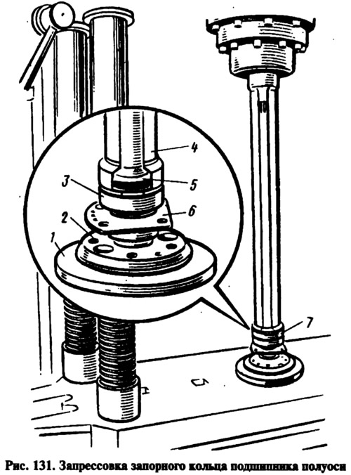
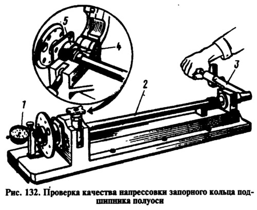
Set vertical axis 2 (pic. 131), resting it with a flange on the ring 1 (A.74107/R) fixtures. Install the semi-axle bearing oil slinger and the fastening plate 6 with the gasket on the semi-axis, which are pre-connected with two screws, install the semi-axis bearing 3. Insert a new locking ring 5 into the special holder 7 (A.74107/4R), put in the oven and heat the ring to approximately 300°C so that at the time of pressing onto the axle shaft its temperature is 220-240°C. Press the locking ring on the axle shaft with a mandrel 4 (A.74107/2R) on a press with a force not exceeding 6000 kgf so that the inner ring of the bearing is sandwiched between the locking ring and the shoulder of the axle shaft. After pressing on, make sure that the ring does not move under an axial load of 2000 kgf. To do this, install the axle shaft assembly on tool A.95601/R (pic. 132), and clamp the locking ring 4 in a special vice, attaching the indicator leg 1, with a division value of 0.01 mm, to the axle shaft flange 2. After setting the indicator needle to zero, apply the specified axial load, creating a tightening torque of 8-8.5 with a torque wrench 3 kgf·m on the fixture screw. The screw through the ball rests against the end of the axle shaft. In this case, even the smallest gap between the locking ring and the inner ring of the bearing 5 should not appear. After removing the load and when the screw of the device is unscrewed, the indicator needle should return to the zero position; this proves that no shift of the axle bearing locking ring has occurred. Otherwise, replace the axle shaft with a new one.