
Disconnect the wires and the vacuum hose from the spark moment sensor. Loosen the mounting nuts and remove the sensor.
The shaft of the spark torque sensor is connected to the camshaft shank in only one position. Therefore, before installation, turn the shaft of the spark moment sensor to such a position that the cams of the shaft coupling are against the grooves of the camshaft.
Put a sealing ring lubricated with engine oil on the flange of the spark torque sensor, install the spark torque sensor on the auxiliary unit housing in such a position that the middle division on the spark torque sensor flange is against the mounting protrusion on the auxiliary unit housing (see fig. 41), and fix the sensor with nuts. Connect wires and a vacuum hose to the spark moment sensor, and then check and, if necessary, adjust the ignition timing.
To replace any parts, disassembly is carried out in the following order.
Remove cover 10 (pic. 157), disconnect the vacuum regulator rod 3 from the base plate 6 of the sensor, unscrew the fastening screws and remove the vacuum regulator. The fastening screws are unscrewed and the base plate 6 is assembled with the sensor 5 and the holder 8. The spring is removed from the clutch 1, the pin is removed and the clutch and shims are removed from the shaft. Take out from the body 2 roller with centrifugal regulator 4 and washers.
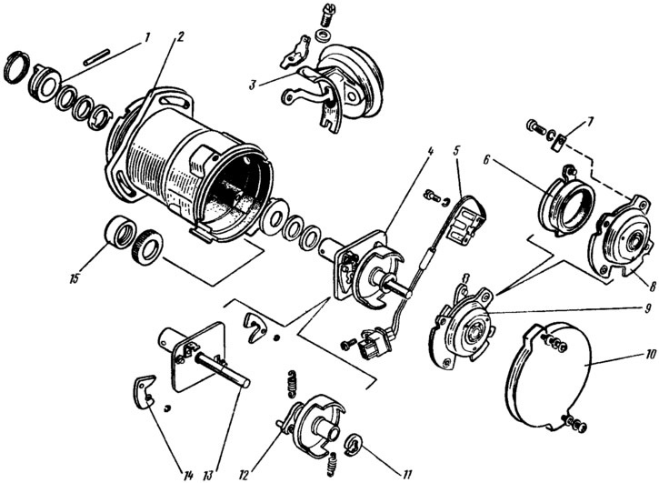
Pic. 157. Details of the spark moment sensor: 1 - clutch; 2 - body; 3 - vacuum regulator; 4 - centrifugal regulator; 5 - proximity sensor; 6 - base plate of the sensor with a bearing; 7 - bearing retainer plate; 8 - holder of the front roller bearing; 9 - holder of the front bearing of the roller assembly with the base plate of the sensor; 10 - cover; 11 - lock washer; 12 - driven plate of a centrifugal regulator with a screen; 13 - roller with the leading plate of the centrifugal regulator; 14 - weight; 15 - stuffing box.
Assembly is performed in the reverse order of disassembly. When assembling, it is necessary to select shims to ensure the axial free play of the roller is not more than 0.35 mm.
Ignition switch
To remove the ignition switch, disconnect the wire from the terminal «minus» battery, remove the steering shaft trim, and disconnect the ignition switch wiring harness from the instrument panel wiring harness.
Insert the key into the ignition switch lock and turn it to position 0, unscrew the bolts securing the switch bracket, remove it, and then the ignition switch.
The ignition switch is installed in the reverse order of removal.
For dismantling the ignition switch KZ813 (Hungarian production) disconnect the wires from the plug, turn the key to position 0 (turned off) and loosen the lock screw. Then, drowning the locking pin, remove the lock with the contact part from the body (there is a hole on the lock body, into which the fixing pin of the lock enters). Unscrew the two fastening screws, disconnect the contact part of the switch from the lock and remove the lining from the contact part. The ignition switch is assembled in the reverse order of disassembly.
The ignition switch 2108-3704005-40 differs in design from KZ813. To disassemble it, it is enough to unscrew one screw, after which the lining and the contact part are disconnected from the switch body.