
Removal and installation of a head of cylinders
On a car, this is done if it is not necessary to remove the engine itself to eliminate the malfunction, or if it is only necessary to remove carbon deposits from the surface of the combustion chamber and valves. The sequence of operations is the following.
Drain the coolant from the radiator and cylinder block, remove the air filter and close the carburetor neck with a technological plug. Disconnect the wires from the battery, spark plugs and from the coolant temperature gauge sensor, disconnect the air damper cable from the carburetor.
Key 67.7812.9514 (tubular face) remove the coolant temperature sensor. Disconnect the throttle actuator links from the intermediate lever on the cylinder head cover and remove the cover.
Set the gear lever to the neutral position and turn the crankshaft until the mark on the camshaft sprocket aligns with the mark on the bearing housing (see fig. 56). This operation is necessary in order to correctly install the camshaft sprocket when installing the cylinder head on the engine.
The hoses are disconnected from the carburetor, the inlet pipe, from the outlet pipe of the cylinder head cooling jacket and from the fluid supply pipe to the heater, and from the exhaust manifold, the bracket for fastening the fluid outlet pipe from the heater, the starter protective shield and the exhaust pipe of the mufflers are disconnected.
The exhaust manifold and intake pipe with the carburetor are best left on the head. It is more convenient to remove them later when disassembling the cylinder head.
Loosen cap nut 5 (see fig. 46) chain tensioner, press the tensioner rod with a mounting blade and fix it with a cap nut. Remove the camshaft sprocket and lower the chain down, preventing it from slipping off the oil pump drive shaft sprocket.
Unscrew the bolts securing the cylinder head to the block and remove the cylinder head and the gasket located between the head and the cylinder block.
Install the cylinder head to the block in reverse order. Before installation, check that the centering sleeves are in place on the cylinder block in the sockets for bolts 7 and 10 (pic. 13, a).
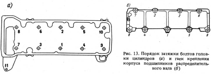
The cylinder head bolts are tightened in a certain sequence (pic. 13, a) in two stages: first tighten bolts 1-10 to 3.4-4.2 kgf·m, and then tighten them to 9.8-12.1 kgf·m, then tighten bolt 11 to 3.2-4, 0 kgf·m.
When installing the camshaft sprocket, it is necessary to pay attention to the coincidence of the alignment marks (see fig. 56 and 57) and tighten the chain, as indicated in sec. 1.11 "Engine settings".
When installing the cylinder head cover with a gasket, the cover fastening nuts should be tightened with a torque of no more than 0.8 kgf·m so as not to cause the gasket to break along the mounting holes and warp the cover. It is recommended to replace the cover gasket with a new one each time the engine is disassembled.
After installing the cylinder head, check and adjust the ignition timing, the gap between the levers and camshaft cams, as well as the drive of the air and throttle valves of the carburetor.
Dismantling and assembly of a head of cylinders
If only a part needs to be replaced, then you can not completely disassemble the cylinder head and remove only the damaged parts. The cylinder head is completely disassembled in the following sequence.
Install the cylinder head on a wooden stand A.60335, unscrew the nuts and remove the carburetor with gasket, intake pipe and exhaust manifold (at the same time the hot air intake is removed). Remove the outlet pipe of the cooling jacket and the fluid outlet pipe to the heater.
Unscrew the fastening nuts and remove the bearing housing with the camshaft and thrust flange.
Remove levers 4 (see fig. 12) valves with springs. Loosen the lock nuts 6 and unscrew the adjusting bolts 5 and, if necessary, their bushings 12. Install the device A.60311 / R, as shown in rice. 12, b, compress the valve springs and release crackers. Instead of the portable tool A.60311/R, the fixed tool 02.7823.9505 can also be used. Remove the valve springs with plates and support washers. Turn the cylinder head and remove the valves from the underside. Remove the oil seals from the guide bushings.
Assemble the cylinder head in reverse order. Before assembly, lubricate the valves and new valve stem seals with engine oil (old ones are not allowed).
The camshaft with bearing housing is installed in the following order. Insert the camshaft lubricated with engine oil into the bearing housing and secure it with a thrust flange. Putting an asterisk on the camshaft (without fixing it) and turn it until the alignment marks on the sprocket and bearing housing are aligned (see fig. 56). Remove the sprocket and, without violating the position of the camshaft, install the bearing housing on the cylinder head.
Check if the mounting sleeves are included (around the studs and in fig. 13b) into the holes of the bearing housing, and then tighten the nuts of the bearing housing in the sequence shown in Fig. 13, b.