
Rear wheel brake
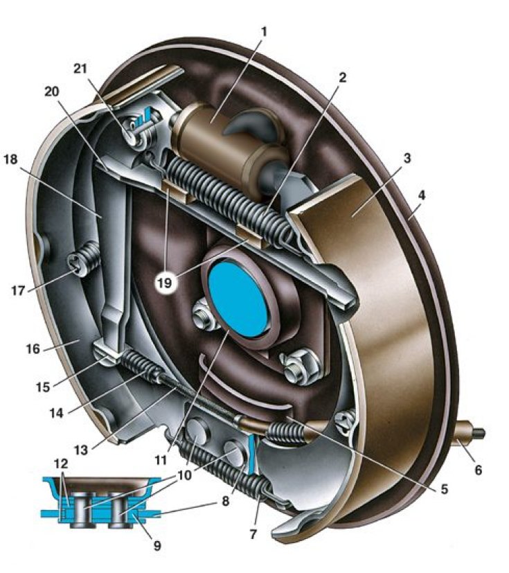
1 – wheel cylinder; 2 – the top coupling spring of pads; 3 - overlay pads; 4 - brake shield; 5 - inner plate; 6 - shell of the rear cable; 7 - the lower coupling spring of the shoes; 8 - front brake shoe; 9 - base plate of pads; 10 - rivets; 11 - oil deflector; 12 - guide plate pads; 13 - rear parking brake cable; 14 – rear cable spring; 15 - tip of the rear cable; 16 - rear brake shoe; 17 - support stand pads; 18 – the lever of a manual drive of pads; 19 - rubber pads; 20 - spacer strip pads; 21 – a finger of the lever of a manual drive of pads
Wheel cylinder
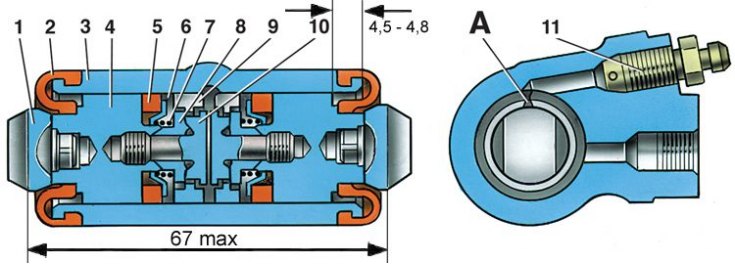
1 - stop pads; 2 - protective cap; 3 - cylinder body; 4 - piston; 5 - sealant; 6 - support cup; 7 - spring; 8 - crackers; 9 - thrust ring; 10 - stop screw; 11 - fitting; A - a slot on the thrust ring
Wheel cylinder parts
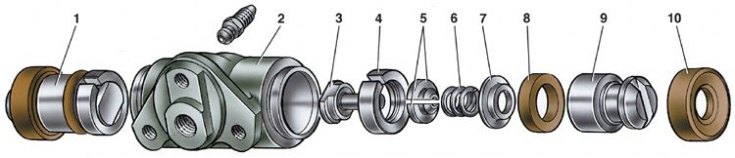
1 - piston assembly; 2 - cylinder body; 3 - stop screw; 4 - thrust ring; 5 - crackers; 6 - spring; 7 - support cup; 8 - sealant; 9 - piston; 10 - protective cap
The brake mechanism of a back wheel of drum type with self-adjusting pads. Brake pads 8 (see fig. Rear wheel brake) with pads, the wheel cylinder 1 and other parts are mounted on the brake shield 4, which is attached to the flange of the rear axle beam.
The clearance between the shoes and the drum is automatically adjusted using a device located in the wheel cylinder 1. Its main element is a split thrust ring 9 (see fig. Wheel cylinder and fig. Wheel cylinder parts), installed on piston 4 (1) between the shoulder of the thrust screw 10 (3) and two crackers 8 (5) with a gap of 1.25–1.65 mm. Thrust rings are installed in the cylinder with an interference fit, providing a shear force of the rings along the cylinder mirror of at least 35 kgf, which exceeds the force on the piston from the coupling springs of the brake shoes.
With the optimal clearance between the pads and the drum, during braking, the pads move apart until a gap of 1.25–1.65 mm is selected between the shoulder of the screw and the shoulder of the thrust ring. The specified clearance allows the pads to travel to generate maximum braking torque.
When the linings are worn, the gap of 1.25–1.65 mm is completely eliminated, the collar on the thrust screw 10 is pressed against the collar of the ring 9, as a result of which the thrust ring is shifted after the piston by the amount of wear. With the cessation of braking, the force of the coupling springs shifts the pistons until the crackers stop against the shoulders of the thrust rings. This maintains optimum clearance in the brake mechanism.