




Open large image in new tab »
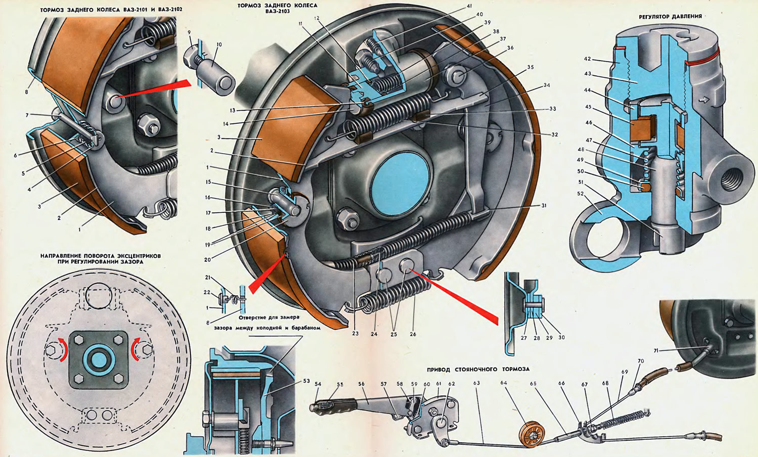
1. Brake shoe rib. 2. Brake shoe rim. 3. Brake shoe lining. 4. Outer thrust cup. 5. Spring. 6. Inner thrust cup. 7. Strut (VAZ-2101). 8. Shield. 9. Eccentric nut. 10. Eccentric (VAZ-2101, VAZ-2102). 11. Piston. 12. Sealing ring. 13. Protective cuff. 14. Piston stop. 15. Axle (VAZ-2103). 16. Bushing nut. 17. Spring. 18. Support cup. 19. Friction washer. 20. Bushing. 21. Fastening spring (VAZ-2103). 22. Eye. 23. Return spring. 24. Rear cable. 25. Rivet. 26. Lower tension spring. 27. Inner plate. 28. Guide plate. 29. Support plate. 30. Outer plate. 31. Tip stirrup. 32. Upper tension spring. 33. Cushion. 34. Brake shoe lever. 35. Expander plate. 36. Lever pin. 37. Wheel cylinder. 38. Support cup. 39. Expansion spring. 40. Pipe nipple. 41. Bleed nipple. 42. Regulator housing. 43. Plug. 44. Bushing. 45. Seal. 46. Plate. 47. Spring. 48. Piston. 49. Seal collar. 50. Seal. 51. Piston tail. 52. Housing eye. 53. Brake drum. 54. Rod button. 55. Rod spring. 56. Parking brake lever. 57. Switch stop. 58. Rod. 59. Pawl. 60. Sector. 61. Bracket. 62. Return lever. 63. Front cable. 64. Guide roller. 65. Front cable end. 66. Bracket. 67. Adjusting nut. 68. Return spring. 69. Cable. 70. Front end. 71. Rear end.
Rear wheel brake mechanism. Brake shoes, wheel cylinder 37 and other parts are mounted on shield 8, which is fastened to the flange of the rear axle beam and is the basic part of the brake mechanism. At the base of the circular flange of the shield, six evenly spaced bosses are stamped around the circumference, which serve as support points for the rims 2 of the brake shoes. A pack of plates is installed on the lower stamping of the shield with two rivets 25, which form the support of the lower ends of the brake shoes. The outer plates 30 and 27 limit the lateral displacement of the brake shoes, and plates 28 limit the lateral displacement of the cable 24.
Wheel cylinder 37 is attached to the upper stamping of the shield. In the side boss of the cylinder body, in addition to the threaded holes for fastening, there is a central hole for supplying brake fluid and an upper hole for bleeding the brake system. Pipe nipple 40 is screwed into the central hole, and nipple 41 for bleeding the brakes is screwed into the upper hole.
Inside the cylinder there are two opposite pistons 11. Stops 14 are pressed into the outer ends of the pistons, into the grooves of which the upper ends of the ribs of the brake shoes rest. The pistons of the wheel cylinder in the non-working state, when there is no brake fluid pressure in the pipelines, are pressed to the brake shoes by the spacer spring 39 through the support cups 38 and sealing rings 12. For the exact position of the spacer spring during assembly, the support cups are pressed onto its ends. The exit of the pistons from the cylinder is protected by rubber cuffs 13, the outer edges of which are thrown over the flanges of the cylinder, and the inner ones - over the journals of the pistons.
The brake shoes of the 8A3-2103 vehicle, mounted on the shield 8, are pulled together by the upper 32 and lower 26 springs. The lower ends of the shoes rest against the plate 29, and the bushings 20 of the automatic adjusting device rest against the axles 15. The upper tension spring is longer than the lower one, therefore, to prevent vibrations and knocking during the movement of the vehicle, it is pressed against two rubber cushions 33. The shoes are held from lateral movement by the grooves of the stops 14, the guide plate 30 and the springs 21, hooked onto the crossbars of the shoe ribs and onto the shield through the ears 22.
The brake shoes of VAZ-2101, 2102 cars in the non-working state are pressed by the upper spring until they stop in the adjusting eccentrics 10 and from lateral movement, in addition to the plate 30 and stops 14, are held by the posts 7. The head of the post is held by the shield 8, and the shoulders, through cups 6 and 4 and spring 5 between them, limit the lateral movement of the shoe. The non-rigid (spring) connection of the brake shoe with the shield allows the shoe to self-adjust at the moment of contact with the surface of the drum 53.
The brake pads are welded. The friction lining 3 is glued to the surface of the rim 2 with special glue BFT-2, and then ground.
The adjusting device installed on each brake shoe of the VAZ-2103 consists of a steel bushing 20, two metal-ceramic friction washers 19, a spring 17 and a nut 16. The friction washers are pressed on both sides to the edge of the brake shoe by the force of the spring compressed by the nut screwed onto the bushing. After screwing in to the stop, the nut 16 is locked from self-unscrewing by rolling out the flange of the bushing 20.
Operating principle of the adjusting device. The brake shoe, with the activation of the brake hydraulic drive, overcoming the resistance of the spring 32 and simultaneously selecting the gap between the axis 15 and the bushing 20, moves until it stops in the brake drum.
If the gap between lining 3 and drum 53 is greater than the gap between axis 15 and bushing 20 (wear of lining, drum), then the shoe, moving until it stops in the drum, overcomes the friction force between the rib 1 and the friction washers 19. When the hydraulic drive stops, the brake shoe is moved away from the drum by the spring 32 only by the amount of the gap (0.8 mm) between the bushing and the axle, since the spring force is insufficient to overcome the friction force in the adjusting device. In this way, the gap between the brake shoe lining and the drum specified by the design is restored as their rubbing surfaces wear out.
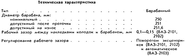
To adjust the gap between the linings 3 and the drum 53 (VAZ-2101 and 2102) adjusting eccentrics 10 are installed, fixed in the shield wall 8 with nuts 9, screwed onto the eccentric tails with a certain tightening torque, which ensures a constant torque of turning the eccentrics (at least 0.65 kgf·m). This is done to prevent spontaneous rotation of the eccentric. To prevent self-unscrewing, nuts 9 are welded to the tails after tightening.
The parking brake includes a mechanical drive from the hand lever 56, located on the floor between the front seats, and the brake mechanism of the rear wheels.
The brake shoes are pressed against the drum when the lever 34 and the expansion bar 35 are moved. The lever 34 is seated on the pin 36 and together with the rib of the brake shoe rests against the groove of the expansion bar. The stirrup 31 of the tip of the steel cable 24 is thrown over the lower end of the lever, made in the form of a hook. The second end of the cable is connected to the brake mechanism of the other wheel. For protection and support against the mounting brackets and brake shields, both knees of the cable are enclosed in a multilayer casing made of plastic tubes and wire braiding. In addition, return springs 23 are put on the ends of the cable, which help the rear cable return to its original position when it is released from force. The rear tip 71 of the casing is fastened to the brake shield 8, and the front tip 70 of the casing rests against the bracket on the bottom of the body.
Before assembly, the rear cable is lubricated with lithium soap-based grease and does not require additional lubrication during operation.
The middle part of the rear cable, free from the sheath, is thrown over the guide bracket 66, which is put on the tip 65 of the front cable 63.
The movement of the cable is guided by a plastic roller 64, and a return spring 68 helps the cable to return to its original position when the lever 56 is released.
The parking brake lever is mounted on bracket 61 and rotates on a shaft, at the other end of which a return lever 62 is mounted. The assembly of the levers with the shaft and bracket is non-detachable.
Inside the lever 56, a pawl 59 swings on the axis, which fixes the lever in a given position and is controlled by the button 54, the rod 58 and the spring 55. The pawl engages with the toothed sector 60, mounted on rivets between the posts of the bracket 61. When the lever 56 is moved upward, the pawl slides freely along the toothed sector. To return the lever to the lower position, it is necessary to press the button 54, thereby releasing the pawl from engagement with the sector.
The tension level of the front 63 and rear 24 cables (therefore, the lever stroke is 56) it is adjusted by tightening or loosening nut 67 with a lock nut.
When a moving vehicle brakes, the load on the axles is redistributed, i.e. the main load is transferred to the front suspension, and the rear suspension is accordingly unloaded, and the grip of the rear wheels on the road surface decreases.
In order to avoid rear wheel skidding during braking and, consequently, possible skidding of the vehicle, a pressure regulator is connected in series to the rear brake hydraulic drive system. Its purpose is to reduce the pressure in the rear wheel hydraulic drive, i.e. to reduce braking efficiency while reducing the load on the rear suspension.
The pressure regulator is mounted on a bracket, which is fixed to the bottom of the body on the right side (in the direction of travel). The regulator is actuated by a two-arm lever, fixed on two supports: one support on the rear panel of the floor, the other support is a pin inserted into the ears 52 of the regulator body.
The long arm of the lever is connected via a stirrup to the rear axle beam. The short arm of the lever rests against the tailstock 51 of the regulator piston and transmits the oscillatory motion of the rear suspension to the piston.
The articulated joints and lever support do not require maintenance during operation, since the rubber bushings of these joints protect the friction surfaces from abrasive particles and moisture.
Steel piston 48 divides the regulator cavity into two cavities - upper and lower and is the main part regulating the bypass of brake fluid from one cavity to another.
The lower cavity is connected to the pipeline coming from the main brake cylinder, and the upper cavity is connected to the pipeline going to the wheel cylinders of the rear brakes.
The article is taken from the website: VazBook.ru
The piston rod outlet from the housing is sealed by a rubber ring 50 with a spheroidal friction surface. Spring 47, resting against floating plate 46 (and through it into the piston shoulders), strives to constantly press the piston until its protrusion rests against plug 43.
The rubber seal 45, on which the piston head sits when the regulator cavities are separated, is also of the floating type, but its movement towards the piston head is limited by the sleeve 44.
When the piston is in the upper (non-working) position, the brake fluid passes from one cavity of the regulator to another through the gaps between the piston rod, plate 46 and seal 45, the piston head, seal and sleeve 44 and then along the groove of plug 43 into the bore of the housing, to the upper opening.