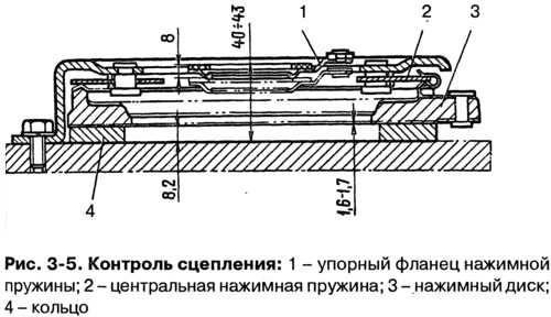
The distance from the base to the working surface of the friction ring of the thrust flange should be 40-43 mm. In the course of work, due to the wear of the friction surfaces of the clutch discs, this size increases. If it reaches 48 mm or the movement of the pressure plate is less than 1.4 mm, replace the clutch cover assembly with the pressure plate.
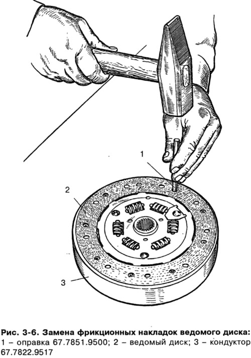
Replace the friction linings of the driven disk if cracks appear, the distance between the rivet and the working surface decreases to 0.2 mm, and also if one-sided scuffing occurs. When repairing the driven disk and replacing the friction linings, use tool 67.7822.9529 (pic. 3-6).
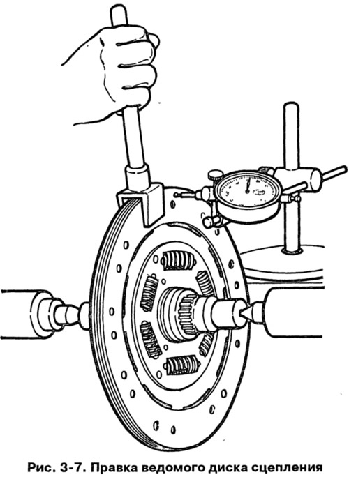
Flared rivets must not be broken. The runout of the working surface of the friction linings should not exceed 0.5 mm. If it is more, then straighten the disk (pic. 3-7) or replace with a new one. If cracks appear on the driven disk or damper springs, replace the driven disk assembly.