
The location of the contact patch in the gearing of the final drive gears
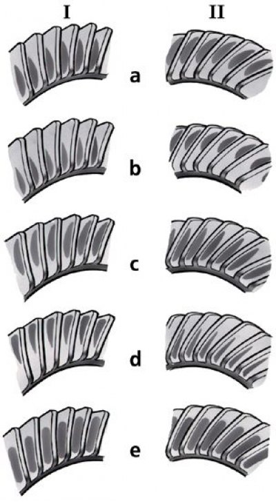
I - forward side;
II - reverse side;
a and b - incorrect contact in the meshing of the gears: move the drive gear away from the driven gear, reduce the thickness of the adjusting ring;
c and d - incorrect contact: move the drive gear to the driven gear, increasing the thickness of the adjusting ring;
e - correct contact in the meshing of gears
1. Install the adjusted gearbox on the stand and lubricate the working surfaces of the driven gear teeth with a thin layer of lead oxide.
2. Start the stand; slow down the rotation of the installed axle shafts with the levers of the stand so that under the load on the surfaces of the teeth of the driven gear there are traces of contact with the teeth of the drive gear.
3. Change the direction of rotation of the stand and, while braking, get contact marks on the other side of the teeth of the driven gear, which corresponds to the movement of the car in reverse.
4. Engagement is considered normal if on both sides of the teeth of the driven gear the contact patch is evenly located closer to the narrow end of the tooth, occupying two-thirds of its length and not reaching the top and bottom of the tooth, as shown in Fig. The location of the contact patch in the meshing of the main gear gears, e.
5. Cases of incorrect divergence of the contact patch on the working surface of the tooth are shown in Fig. The location of the contact patch in the gearing of the final drive gears (a, b, c, d).
6. To adjust the correct position of the drive gear with the replacement of the ring, disassembly of the assembly is necessary.
7. When assembling, repeat all the operations for preloading the roller bearings of the drive gear, checking the moment of resistance to rotation, preloading the roller bearings of the differential box, and adjusting the side clearance of the engagement of the final drive gears.