
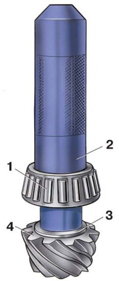
Rear axle gear parts
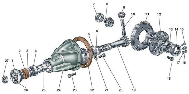
1 - drive gear flange; 2 - stuffing box; 3 - oil deflector; 4 - front bearing; 5 - rear bearing; 6 - adjusting ring of the drive gear; 7 - support washer of the axle gear; 8 – half shaft gear; 9 - satellite; 10 – satellite axis; 11 - driven gear; 12 - differential box; 13 - differential box bearing; 14 - adjusting nut; 15 – a bolt of fastening of a locking plate; 16 - locking plate; 17 - locking plate; 18 – a bolt of fastening of a conducted gear wheel to a differential box; 19 - drive gear; 20 – cover fastening bolt; 21 - spring washer; 22 - gasket; 23 – a bolt of fastening of a reducer to a beam of the back bridge; 24 - gearbox housing; 25 - spacer sleeve; 26 - flat washer; 27 – a nut of fastening of a flange of a leading gear wheel
Reliable operation of the gearbox is ensured by strict adherence to the following assembly and adjustment procedures.
Differential Assembly
1. Lubricate with gear oil and install through the windows in the differential box the gears of the axle shafts with support washers and satellites.
2. Turn the satellites and gears of the axle shafts so as to align the axis of rotation of the satellites with the axis of the hole in the box, then insert the axis of the satellites.
3. Check the axial clearance of each gear of the axle shaft: it should be 0–0.10 mm, and the moment of rotation resistance of the differential gears should not exceed 14.7 Nm (1.5 kgf·m).
4. If the clearance is increased, which is a sign of wear of the differential parts, replace the bearing washers of the gears of the axle shafts with others of greater thickness. If the specified clearance cannot be obtained even with the thickest washers installed, replace the gears with new ones due to excessive wear.
5. Install the driven gear on the differential case.
6. Using mandrel A.70152, press the inner races of roller bearings onto the differential box.
Installing and adjusting the drive gear
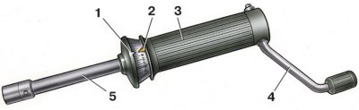
Final drive gears
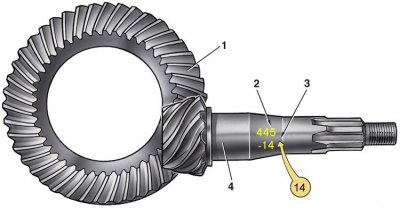
1 - driven gear; 2 - serial number; 3 - correction in hundredths of a millimeter to the nominal position; 4 - drive gear
The correct position of the drive gear relative to the driven gear is ensured by selecting the thickness of the adjusting ring installed between the thrust end of the drive gear and the inner ring of the rear bearing.
Select the adjusting ring using the mandrel A.70184 and tool A.95690 with indicator.
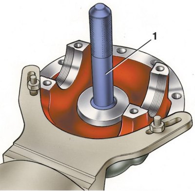
1. Having fixed the crankcase on the stand, press the outer rings of the front and rear bearings of the drive gear into the housings of the crankcase, using mandrels for this: for the front bearing - A.70185, and for the rear - A.70171 (1).
2. On mandrel А.70184 (4), simulating the drive gear, use the mandrel A.70152 to install the inner ring of the rear bearing (3) and insert the mandrel into the neck of the gearbox housing (2 - adaptation A.95690).
3. Install the front bearing inner ring, drive gear flange and, turning the mandrel to properly install the bearing rollers, tighten the nut to a torque of 7.8–9.8 N·m (0.8–1 kgf·m).
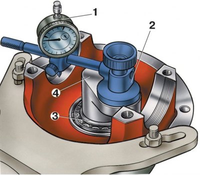
4. Fix fixture A.95690 on the end of mandrel 4 and adjust indicator 1, which has divisions of 0.01 mm, to the zero position by placing its leg on the same end of mandrel A.70184. Then move the indicator so that its leg rests on the seating surface of the bearing of the differential box (see fig. in paragraph 2).

5. Turning mandrel 1 with indicator left and right, set it to a position where the indicator arrow marks the minimum value "a1" and write it down. Repeat this operation on the seat of the second bearing and determine the value "a2" (2 - adaptation A.95690).
6. Determine thickness "S" adjusting ring of the drive gear, which is the algebraic difference between the values "A" And "b":
S = a - b, where:
- a - arithmetic mean distance from the ends of the mandrel 1 to the necks of the differential bearings;
– a = (a1 a2) / 2;
- b - deviation of the drive gear from the nominal position, translated in mm. (see fig. in paragraph 5).
7. The amount of deviation is marked on the drive gear (see fig. final drive gears) in hundredths of a millimeter with a plus or minus sign.
8. When determining the thickness of the adjusting ring, consider the sign of the value "b" and its unit of measurement.
Example
Let's assume that the value "A", set using the indicator, is equal to 2.91 mm (magnitude "A" always positive), and on the drive gear after the serial number the deviation is set "-14". To get the value "b" in millimeters, you need to multiply the indicated value by 0.01 mm.
b= -14 0.01 mm= -0.14 mm
Determine the thickness of the adjusting ring for the pinion in millimeters.
S = a – b = 2.91 mm – (-0.14mm) = 2.91 mm + 0.14 mm = 3.05 mm
In this case, install a 3.05 mm thick adjusting ring.
9. Put on the drive gear (4) adjusting ring (3) desired thickness and press on with mandrel A.70152 (2) rear inner ring (1) bearing removed from mandrel A.70184. Put on the spacer sleeve.
10. Insert the drive gear into the gear housing and install the front bearing inner race, oil slinger, oil seal, drive gear flange and washer onto it.
11. Screw a nut onto the end of the gear and, locking the flange of the drive gear, tighten it (tightening torque see below).
Pinion bearing adjustment
Dynamometer 02.7812.9501
1 - movable pointer; 2 - torque limit indicator; 3 - body; 4 - handle; 5 - a rod with a tip inserted into the adapter sleeve of the nut of the pinion flange
1. To limit the axial displacements of the drive gear under operating loads, it is very important to create a preload in its bearings within the specified limits. Preload is controlled by a dynamometer 02.7812.9501 (see fig. Dynamometer 02.7812.9501), measuring the moment of resistance to turning the drive gear.
2. The torque of resistance to rotation determines the degree of tightening of the bearings. It should be 157–198 Ncm (16–20 kgf cm) for new bearings and 39.2–58.6 Ncm (4–6 kgf cm) for bearings after a run of 30 km or more.
3. Tighten the flange nut with a torque of 117–255 N·m (12–26 kgf·m), periodically checking with a dynamometer the moment of resistance of the bearings to turning the drive gear.
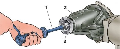
4. To check the moment of resistance, put a dynamometer 1 on the adapter sleeve 3 (2 - crankcase).
5 Set Pointer 2 (see fig. Dynamometer 02.7812.9501) torque limit per scale division corresponding to 196 Ncm (20 kgf cm), and turn knob 4 a few turns clockwise.
6. While turning the drive gear, the movable pointer 1 must not go beyond the pointer 2 and must show at least 157 N cm (16 kgf cm).
7. If the torque is less than 157 Ncm (16 kgf cm), and for bearings after a run of 30 km or more - 39.2 N cm (4 kgf cm), then tighten the pinion flange nut (without exceeding the specified tightening torque) and check again the moment of resistance to turning the drive gear.
8. If the moment of resistance to rotation is more than 198 Ncm (20 kgf cm), and for run-in bearings 58.8 N cm (6 kgf cm), indicating that the bearing preload is too high, replace the spacer sleeve, as it has deformed from excessive load to a size that does not allow for correct adjustment.
9. After replacing the spacer sleeve, repeat assembly with appropriate adjustments and checks.
Installing the differential box
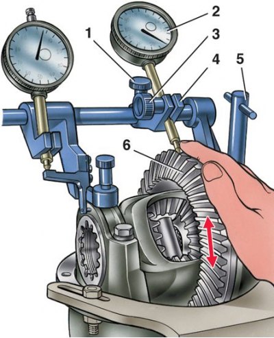
Checking the preload of the bearings of the differential box with the tool A.95688 / R
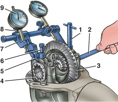
1 - fastening screw; 2 - key A.55085; 3 - driven gear; 4 - adjusting nut; 5 - intermediate lever; 6 - fastening screw; 7 – indicator bracket; 8 – bracket tightening screw; 9 - indicator for checking the preload of the bearings of the differential box
Checking the lateral clearance in the gearing of the final drive gears using A.95688 / R
1 – bracket tightening screw; 2 - indicator for checking the side clearance in the meshing of the driving and driven gears; 3 - screw for fastening the indicator rod; 4 – indicator bracket; 5 - fastening screw; 6 - driven gear
1. Install the pre-assembled differential case in the crankcase together with the bearing outer races.
2. Install two adjusting nuts 4 (see fig. Checking the preload of the bearings of the differential box with the tool A.95688 / R) so that they are in contact with the bearing rings.
3. Install the bearing caps and tighten the mounting bolts with a torque wrench.
4. Preload of bearings of the differential box and adjustment of the backlash in the meshing of the final drive gears. These operations are carried out simultaneously with the help of the A.95688/R tool and the A.55085 key.
5. Attach the tool to the gearbox housing (see fig. Checking the preload of the bearings of the differential box with the tool A.95688 / R) screws 1 and 6, screwing them into the holes for the bolts of the locking plates of the adjusting nuts.
6. Move bracket 7 along the guide of the fixture until the lever touches the outer side surface of the cover and tighten screw 8. Loosen screws 1 and 3 (see fig. Checking the lateral clearance in the gearing of the final drive gears using A.95688 / R), and install bracket 4 so that the indicator leg rests on the side surface of the driven gear tooth at the edge of the tooth, then tighten screws 1 and 3.
7. By turning the adjusting nuts, pre-adjust the backlash between the teeth of the driving and driven gears within 0.08–0.13 mm. The gap is checked by indicator 2 while rocking gear 6. In this case, the bearings should not have a preload.
8. The adjusting nuts must only be in contact with the bearings, otherwise the correct preload measurement will be impaired.
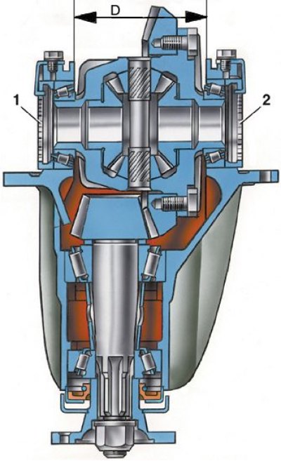
9. Tighten the two bearing adjusting nuts sequentially and evenly (1, 2), while the differential bearing caps diverge, therefore, the distance increases "D". This discrepancy is marked by indicator 9 (see fig. Checking the preload of the bearings of the differential box with the tool A.95688 / R), on the leg of which lever 5 acts.
10. Nuts for adjusting the bearings of the differential box are tightened to increase the distance "D" (see fig. in paragraph 9) by 0.14–0.18 mm.
11. Having set the exact preload of the bearings of the differential box, finally check the backlash in the meshing of the final drive gears, which should not change.
12. If the gap in the meshing of the gears is more than 0.08–0.13 mm, then move the driven gear closer to the drive gear or move it away if the gap is smaller. To maintain the set bearing preload, move the driven gear by tightening one of the bearing adjusting nuts and loosening the other by the same angle.
13. To accurately perform this operation, watch the indicator 9 (see fig. Checking the preload of the bearings of the differential box with the tool A.95688 / R), which shows the previously set bearing preload.
14. After tightening one of the nuts, the indicator reading will change, as the discrepancy will increase "D" (see fig. in paragraph 9) caps and bearing preload. Therefore, loosen the other nut until the indicator arrow returns to its original position.
15. After moving the driven gear on the indicator 2 (see fig. Checking the lateral clearance in the gearing of the final drive gears using A.95688 / R) check the side clearance. If the clearance is not correct, repeat the adjustment.
16. Remove tool A.95688/R, install the locking plates of the adjusting nuts and secure them with bolts and spring washers. Spare parts are supplied with locking plates of two types: with one or two tabs, depending on the position of the nut slot.
17. The adjustment and repair of the gearbox units is carried out on the stand, where you can also test the gearbox for noise and check the location and shape of the contact patch on the working surfaces of the teeth, as indicated in subsection 5.4.7.7.