
Spark torque sensor
When removing the characteristics of automatic ignition timing, a sparking moment sensor is installed on a stand for testing electrical appliances and connected to an electric motor, the rotational speed of which is adjustable.
Connect the sensor leads to the leads «3», «5» and «6» stand switch. Conclusion «4» stand switch must be connected to the terminal «+» stand, and output «1» - with clamp «breaker» stand.
The electric motor of the stand is turned on and the shaft of the sparking moment sensor is rotated with a frequency of 500-600 min-1. On the graduated disk of the stand, the value in degrees is noted at which one of the contactless sensor pulses is observed (it will be zero).
Increasing the speed in steps by 200-300 min-1, determine the number of degrees of ignition advance on the disk, corresponding to each frequency of rotation of the shaft of the spark moment sensor. Then, reducing the speed of the roller, make sure that at a speed of 500-600 min-1 sparking moment returns to zero. The obtained characteristic of the centrifugal ignition timing controller is compared with the characteristic in fig. 153, a.
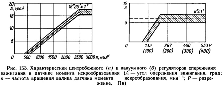
If the characteristic does not match, then it can be brought back to normal by bending the spring racks of the weights of the centrifugal regulator. Up to 1500 min-1 bend the rack of a thin spring, and over 1500 min-1 - thick. To decrease the angle, increase the tension of the springs, and to increase it, decrease it.
To measure the characteristics of the vacuum ignition timing regulator, connect the vacuum regulator fitting to the stand vacuum pump. Turn on the electric motor of the stand and rotate the shaft of the ignition distributor with a frequency of 1000 min-1. On a graduated disk, note the value in degrees at which one of the proximity sensor pulses is observed.
Gradually increasing the vacuum, every 67.0 Pa mark the number of degrees of ignition advance relative to the initial value. The resulting characteristic is compared with the characteristic in Fig. 153, 6. Within a small range, you can adjust the characteristic of the vacuum regulator by moving its body. If this method fails to bring the characteristic to normal, then the vacuum regulator is replaced. When taking the characteristic, it is necessary to pay attention to the clarity of return to the initial position after the removal of the vacuum of the base plate of the non-contact sensor.
Checking the proximity sensor
From sensor output (between green and white-black wires) stress is relieved if there is a steel screen in its gap. If there is no screen in the gap, then the voltage at the output of the sensor is close to zero.
On the sparking moment sensor removed from the engine, the sensor can be checked according to the diagram shown in fig. 154, a, at a supply voltage of 8-14 V. Slowly rotating the shaft of the spark moment sensor, measure the voltage at the sensor output with a voltmeter. It should change sharply from the minimum - no more than 0.4 V to the maximum - no more than 3 V below the supply voltage.
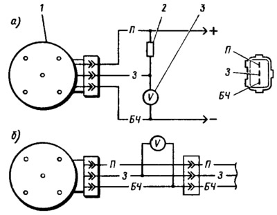
Pic. 154. Schemes for checking the proximity sensor on the removed spark torque sensor (A) and by car (b): 1 - spark moment sensor; 2 - resistor 2 kOhm; 3 - voltmeter with a scale limit of at least 15 V and an internal resistance of at least 100 kOhm.
On the car, the sensor can be checked according to the diagram shown in fig. 154b. An adapter with a voltmeter is connected between the plug of the spark moment sensor and the connector of the wire bundle. Turning on the ignition, slowly turning the crankshaft with a special key, check the voltage at the sensor output with a voltmeter. It must be within the above limits.
Ignition coil
Check the resistance of the windings, whether there is a short circuit between the windings and breakdown of the insulation on the case. The resistance of the primary winding at 25°C should be (0,5±0,05) Ohm, and the secondary winding (11±1,5) kOhm Insulation breakdown on the housing is detected by burnout or melting of the plastic winding of the coil on the surface adjacent to the mounting bracket.
Switch. The switch is checked using an oscilloscope and a square-wave generator according to the circuit shown in fig. 155. It is desirable to use a two-channel oscilloscope. One channel is used to monitor the generator pulses, and the second channel is used to monitor the commutator pulses.
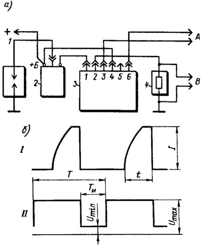
Pic. 155. Scheme for checking the switch (A) and the shape of the pulses on the oscilloscope screen (b): 1 - arrester; 2 - ignition coil; 3 - switch; 4 - resistor 0.01 Ohm±1% ≥ 20 W; A - to the generator of rectangular pulses; B - to the oscilloscope; I - commutator impulses; II - generator pulses; t is the current accumulation time; I is the maximum current value.
When assembling the circuit to test the switch, make sure that the low voltage wires are not in the same bundle with the high voltage wires. In addition, it is not allowed to disconnect the plug connector from the switch when the ignition is on (when power supply is on), since in this case voltage up to 400 V may occur on individual elements of the switch circuit and the switch will be damaged.
On terminals «3» and «6» The switch receives rectangular pulses with a frequency of 3.33 to 233 Hz from the generator, simulating sensor pulses. Pulse duty cycle, i.e. the ratio of the period to the pulse duration T / Tn=3. Maximum voltage Umax=10 V, and the minimum Umin≤0.4V (see fig. 155). The output impedance of the generator should be 100-500 ohms.
For a working switch, the shape of the current pulses should correspond to waveform 1.
For switches 36.3734 and 3620.3734 with a supply voltage of 13+0,1 The value of the current I should be 7.5–8.5 A. The current accumulation time t for the switch 36.3734 should be no more than 7.8 ms at a frequency of 33.3 Hz and no less than 3.2 ms at a frequency of 150 Hz. For the switch 3620.3734, the current accumulation time is not standardized.
For HIM-52 switch at supply voltage (13,5 ±0,2) The current value should be 8-9 A, and the accumulation time 8-10.5 ms at a frequency of 25 Hz. For the BAT 10.2 switch, with the same supply voltage and frequency, the current strength is 7–8 A, and the accumulation time is 5.5–7.5 ms.
If the shape of the commutator pulses is distorted, then there may be interruptions in sparking or it may occur with a delay. In this case, the engine will overheat and not develop rated power.
Spark plug
Before testing, spark plugs with carbon deposits or contaminated ones are cleaned in a special installation with a jet of sand and blown with compressed air. If the soot is light brown in color, then it can not be removed, since it appears on a working engine and does not disrupt the operation of the ignition system.
After cleaning, inspect the candles and adjust the gap between the electrodes. If there are chips, cracks on the spark plug insulator, or the side electrode welding is damaged, then the spark plug is replaced.
Gap (0.7—0.8 mm) between the electrodes of the candle is checked with a round wire probe. It is impossible to check the gap with a flat probe, since this does not take into account the recess on the side electrode, which is formed during the operation of the candle. The gap is adjusted by bending the side electrode of the spark plug.
Leak test
Screw the candle into the corresponding socket on the stand and tighten with a torque wrench to a torque of 31.4-39.2 N·m. Then a pressure of 2 MPa is created in the stand chamber. Drop a few drops of oil or kerosene on the candle; if the tightness is broken, then air bubbles will come out between the insulator and the metal body of the candle.
Electrical test
Screw the candle into the socket on the stand and tighten to the above torque. The gap between the electrodes of the arrester is adjusted by 12 mm, which corresponds to a voltage of 22 kV, and then a pressure of 0.6 MPa is created in the chamber by a pump. Install the tip of the high voltage wire on the candle and apply high voltage pulses to it.
If a full-fledged spark is observed in the eyepiece of the stand, then the candle is considered excellent. In this case, irregular sparks are allowed on the arrester. If sparking occurs only between the electrodes of the spark gap, then the pressure in the chamber is lowered and the pressure at which sparking occurs between the spark plug electrodes is checked. If it starts at a pressure below 0.3 MPa, then the candle is defective.
If there is no sparking on the spark plug and on the spark gap, then it is most likely that the spark plug insulator has cracks and that the discharge occurs internally between the body and the electrodes. Such a candle is considered defective.
Ignition switch
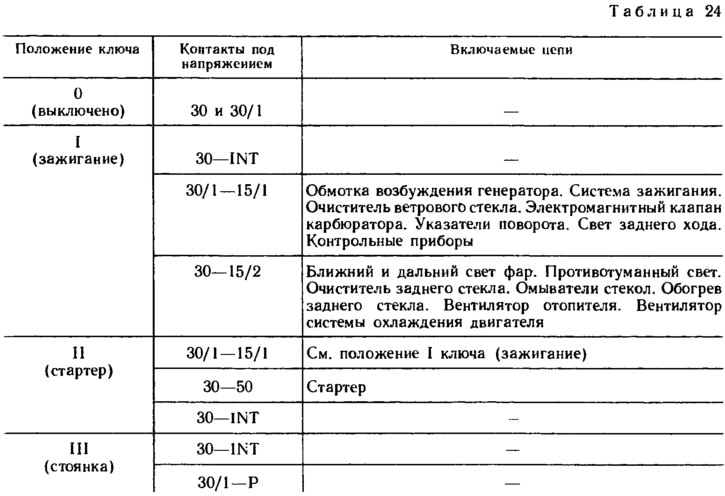
At the ignition switch, the correct closure of the contacts is checked at various key positions (tab. 24), the operation of the anti-theft device and the operation of the blocking device against restarting the starter. The connection diagram of the ignition switch is shown in fig. 156.
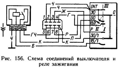
The locking rod of the anti-theft device must extend when the key is set to position III (parking) and take it out of the castle. The locking rod must retract after turning the key from position III to position 0 (turned off). The key must only be removed from the lock in position III.
The locking device against restarting the starter must not allow the key to be turned again from position I (ignition) to position II (starter). Such a turn should only be possible after the key has been previously returned to position 0 (turned off).
Checking elements for suppression of radio interference
These elements include noise suppression resistors with a resistance of 4-10 kOhm in spark plugs, a 2.2 microfarad capacitor located in the generator, and high voltage wires with a resistance distributed along the length, which is (2000±200) Ohm/m for wires PVVP-8 and (2550±270) Ohm/m for wires PVPPV-40.
The serviceability of wires and resistors is checked with an ohmmeter, and checking the capacitor is described in Sec. «Generator».