




Attention. Since the VAZ-2108 uses a high-energy ignition system, it is not allowed to disconnect high-voltage wires and check the ignition circuits for sparks while the engine is running, as this may lead to injuries, as well as burnout of high-voltage insulation and failure of the ignition system.
For the same reason, it is not allowed to start the engine using a spark gap between the high-voltage wire and the central terminal of the ignition distributor sensor.
When servicing your vehicle, check the reliability of the high-voltage wire connections to the ignition distributor, coil and spark plugs.
Do not disconnect the wires from the battery terminals while the engine is running, as this may damage the switch.
Contactless sensor
The operability of the contactless sensor located in the ignition distributor sensor can be checked using an indicator assembled according to the circuit shown in Figure 138. The indicator uses resistors of the MLT type, 1 W; capacitors C1 of the KLS1 type and C2 of the K. 53-14 type. The HL1 indicator lamp is A12 car lamp, 3 watts. Instead of the KT816B transistor, you can use a KT814B transistor. The indicator wires are soldered to a three-terminal block W1 of the same type that is attached to the ignition switch sensor on the car.
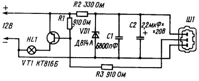
Figure 138. Indicator diagram for checking the functionality of the contactless sensor in the ignition distributor sensor
To check the contactless sensor, connect the indicator to the ignition distributor sensor instead of the ignition system wiring harness and turn the engine with a starter or a special key for the bolt on the crankshaft. If the HL1 lamp blinks when the crankshaft rotates, then the contactless sensor is working properly.
The serviceability of the contactless sensor can also be checked using a voltmeter according to the diagram shown in figure 140.6. The procedure for checking is described in the next chapter. This method is more accurate, as it allows you to check the magnitude of the voltage pulses emitted by the sensor using a voltmeter.
Switch
The operability of the switch can also be checked using a lamp of the A12 type, 3 W. To check, disconnect the brown wire with red stripes from the ignition coil, coming from the terminal "1" of the switch, and connect the tip of the wire to the test lamp. The other terminal of the lamp is connected to the terminal "DB" of the ignition coil and the engine is turned over with the starter. If the lamp blinks when the engine crankshaft is turned, then the switch sends current pulses to the ignition coil.
The described method allows only a rough estimate of the switch's performance - whether it produces current pulses or not. Pulse parameters (size and duration, shape) cannot be checked by this method. And they can seriously affect the engine operation, especially at high crankshaft speed. Therefore, the following test of the switch on the stand using an oscilloscope and a rectangular pulse generator is more accurate.
Ignition coil and high tension wires
The performance of these elements can be checked using a high-voltage arrester. The simplest arrester consists of two pointed metal rods, the gap between which can be adjusted. The rods are fixed to a plate made of electrically insulating material (plastic or ceramic).
To check the ignition coil, disconnect the high-voltage central wire from the ignition distributor sensor and connect it to the spark gap electrode. Connect the second terminal of the spark gap to the car body and set the air gap between the spark gap electrodes to 7-10 mm. If, when the engine is rotated by the starter, uninterrupted sparking is observed between the spark gap electrodes, then the ignition coil and high-voltage central wire are in good condition.
By connecting the central wire to the ignition distributor and connecting the wires going to the spark plugs to the spark gap one by one, the functionality of these wires is checked in the same way. In this case, a violation of spark formation may be observed when all the wires are connected, while spark formation was normal when the central wire was connected to the spark gap. The cause of this phenomenon may be internal discharges in the ignition distributor. It is possible that there are cracks or burnouts in the cover or rotor of the ignition distributor, or their surfaces are dirty. You can verify the presence of this defect by replacing the ignition distributor with a known good one.
Attention. It is strictly forbidden to perform preventive maintenance on the distributor sensor with the ignition on, since the ignition system on the VAZ-2108 is a source of particularly high voltage.