




Open large image in new tab »
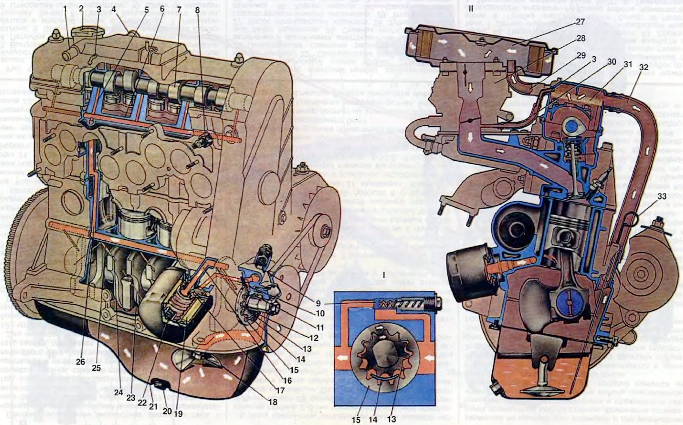
Figure 10. Engine lubrication system: 1. Crankcase gas outlet pipe to the air filter housing; 2. Oil filler cap; 3. Crankcase gas suction pipe into the carburetor throttle space; 4. Exhaust hose branch; 5. Oil supply channel to the camshaft bearings; 6. Oil line in the cylinder head; 7. Camshaft; 8. Oil pressure indicator sensor; 9. Pump pressure reducing valve; 10. Oil supply channel from the pump to the filter; 11. Front crankshaft oil seal; 12. Oil supply channel from the oil receiver to the pump; 13. Oil pump drive gear; 14. Crescent-shaped protrusion between gears; 15. Driven gear of oil pump; 16. Oil supply channel from the filter to the main oil line; 17. Anti-drain valve; 18. Oil receiver; 19. Cardboard filter element; 20. Drain plug; 21. Oil pan; 22. Bypass valve; 23. Oil supply channel from the main bearing to the connecting rod bearing; 24. Oil supply channel to the crankshaft main bearing; 25. Main oil line; 26. Oil supply channel to the cylinder head oil line; 27. Air filter; 28. Carburetor; 29. Hose for removing crankcase gases into the air filter housing; 30. Hose for removing crankcase gases into the carburetor throttle space; 31. Oil separator mesh; 32. Crankcase exhaust hose; 33. Oil level indicator; I. Scheme of operation of the oil pump; II. Engine crankcase ventilation diagram.
The engine lubrication system is combined, in which some parts are lubricated under pressure, and some by gravity and splashing. The capacity of the lubrication system is 3.5 l.
The main and connecting rod bearings of the crankshaft and the camshaft supports are lubricated under pressure.
The oil flowing out of the gaps and splashed by the moving parts lubricates the cylinder walls, pistons with piston rings, piston pins in the piston bosses, camshaft cams, valve tappets, and also the valve stems in their guide bushings.
The lubrication system includes an oil sump 21, an oil pump with a pressure-reducing valve 9 and an oil receiver 18, a system of oil channels, a full-flow oil filter with a filter element 19, a bypass valve 22 and an anti-drain valve 17, an oil level indicator 33 and an oil filler neck.
The oil pressure is monitored by sensor 8, which is screwed into the hole of the oil line in the cylinder head, connected to the main oil line in the cylinder block. The pressure should be 4.5 kgf/cm² at a crankshaft speed of 5600 rpm. The minimum oil pressure should be no less than 0.8 kgf/cm² at 750-800 rpm. When the oil pressure drops below the permissible limit, the oil pressure indicator lamp and the "STOP" light panel in the instrument cluster light up red. Oil circulation during engine operation occurs as follows. The oil pump, located at the front end of the crankshaft, sucks oil through the filter screen of the oil receiver 18, the receiving tube and channel 12 into the pump body and feeds it through channels 10 in the cylinder block to the full-flow filter. In the filter, the oil is cleaned of mechanical impurities and resinous substances. The filtered oil enters the main oil line 25 along the cylinder block via channel 16, and from there it is supplied to the main bearings of the crankshaft via channels 24 in the partitions of the cylinder block. There are two holes in the main bearing shells, through which the oil penetrates into the annular grooves on the inner surface of the shells. From these grooves, part of the oil goes to lubricate the main bearings, and the other part goes to the bearings of the lower heads of the connecting rods via channels drilled in the journals and cheeks of the crankshaft. A stream of oil from the side hole of the connecting rod bearing hits the cylinder wall at the moment the bearing hole coincides with the channel in the connecting rod journal.
The oil removed from the cylinder walls by the oil scraper ring is diverted through holes in the piston into the piston and lubricates the piston pin bearings in the piston bosses.
In the connecting rod journals of the crankshaft, centrifugal cleaning of oil from foreign inclusions contained in the oil occurs, which accumulate in inclined channels under the action of centrifugal forces in the space from the holes in the connecting rod journal to the plug of the crankshaft oil channel.
From the main oil line 25, oil is supplied through vertical channels 26 in the block and cylinder head to the oil line 6 of the cylinder head, and from there through channels 5 to the camshaft bearings. The oil flowing out of the camshaft bearings lubricates the working surfaces of the cams and valve tappets.
The engine oil pump is assembled in a special housing attached to the front wall of the cylinder block. The oil pump is single-section, gear-type, with internal engagement gears. The leading gear 13 of the oil pump is installed on the front end of the crankshaft.
The driven gear 15 is located in the oil pump housing. To ensure the necessary clearances between the gears and the housing when the temperature changes, the housing is cast from cast iron, the gears are made of metal ceramics. In the housing, the suction cavity is separated from the discharge cavity by a sickle-shaped projection 14.
A pair of pump gears rotates in the housing with a clearance of 0.03-0.08 mm in height and 0.10-0.176 mm in diameter of the driven gear. The maximum permissible clearances in the coupling are 0.12-0.15 mm in height and 0.30 mm in diameter.
When the engine is running (see the oil pump diagram) the leading 13 and driven 15 gears of the pump suck in oil and force it into the pump discharge cavity with the tooth cavities. At a pressure above 4.5 kgf/cm², the pressure reducing valve 9 opens and some of the oil is bypassed from the pressure cavity into the pump suction cavity.
The oil filter is screwed onto the nipple and pressed against the annular flange on the block. The tightness of the connection is ensured by a rubber gasket installed between the filter cover and the block flange. Oil enters the filter through channel 10 and, having passed through paper filter element 19, exits into the main line of the block through the central hole, the fastening nipple and channel 16.
the filter has an anti-drain valve 17, which prevents oil from draining from the system when the engine is stopped, and a bypass valve 22, which is triggered when the filter element is clogged and bypasses oil in addition to the filter into the oil line.
Engine crankcase ventilation system
Forced crankcase ventilation removes gases and gasoline vapors from the crankcase, sucking them into the intake tract and engine cylinders, thereby increasing the service life of the oil and increasing the durability of the engine. In addition, crankcase ventilation prevents pressure in the crankcase from increasing due to the penetration of exhaust gases into it. And since the ventilation system is closed, it eliminates the ingress of crankcase gases into the car interior, and the emission of toxic substances into the atmosphere is reduced.
Ventilation is carried out by sucking out crankcase gases through exhaust hose 32, through mesh 31 of the oil separator, hose 29 into the air filter housing, and also through hose 30 into the throttle space of the carburetor.
The original is available on the website: www.VAZbook.ru