English Русский
Български
Беларускі
Український
Српски
Hrvatski
Română
Polski
Slovenský
Magyar
| Articles | Contacts | Sitemap |   
Repair and maintenance Lada Repair and maintenance Mazda Repair and maintenance Mitsubishi Repair and maintenance Toyota Repair and maintenance Land Rover Repair and maintenance Hyundai Repair and maintenance Nissan
VAZbook.ru


Main     1111   2101   2105   2106   2107   2109   2110   2115   2121  
VAZ-2108 (1984-2003) VAZ-2109 (1984-1997) VAZ-21099 (1990-2004)
  • Main
  • «Sputnik»
  • VAZ-2109
  • Power unit
  • Supply system
  • Fuel pump device

Fuel pump device (VAZ-2109)

            0

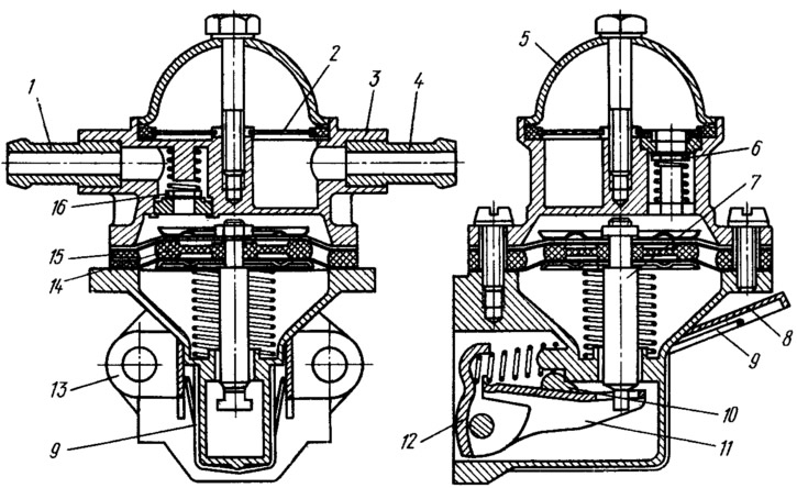
Fuel pump (figure 40) diaphragm type, with mechanical drive, equipped with a manual pumping lever. Capacity 60 l/h at a camshaft speed of 2000 rpm. Driven by a pusher from the camshaft eccentric. This pump is installed on all the vehicles under consideration. A heat-insulating spacer and adjusting linings are installed between the pump and the drive housing.

Figure 40. Fuel pump:

Figure 40. Fuel pump:
1 - discharge pipe; 2 - filter; 3 - upper body; 4 - suction pipe; 5 - lid; 6 - suction valve; 7 rod; 8 - manual fuel pumping lever; 9 - spring; 10 cam; 11 - balance beam; 12 - lever of mechanical fuel pumping; 13 - lower body; 14 - internal spacer gasket; 15 - spring spacer; 16 - discharge valve.


The fuel pump consists of a lower housing 13 with drive levers, an upper housing 3 with valves and pipes, a diaphragm unit and a cover 5. Three diaphragms are installed between housings 3 and 13: two upper ones — working ones — for fuel supply, a lower one — safety one — to prevent fuel from entering the drive housing if the working diaphragms are damaged. The diaphragms are made of membrane fabric. Between the working and safety diaphragms, there are outer 15 and inner 14 spacer gaskets. The outer gasket has an opening for fuel to exit if the working diaphragms are damaged. The diaphragms with plates are installed on the rod 7 and fastened from above with a nut. There is a compressed spring on the rod under the diaphragm unit. The rod with a T-shaped tailpiece is inserted into the slot of the balancer 11, which allows the diaphragm unit to be removed without disassembling.


Levers 12.8 and balancer 11 are installed in the lower housing. Valves are installed in the upper housing 3: suction 6 and discharge 16. Gaskets made of diaphragm material are placed under the valves. The valves are pressed against the seats by springs. Cover 5 is attached to the pump housing from above with a central bolt. A plastic mesh filter is installed between the cover and the housing. Upper housing 3 has discharge 1 and suction 4 pump branches.

When the engine is running, the camshaft eccentric acts on the lever 12 via the pusher and turns the balancer 11, which pulls the pump diaphragms. In this case, the diaphragm spring is compressed. The diaphragms create a vacuum, as a result of which the fuel through the suction valve 6 fills the working cavity of the pump above the diaphragms. When the eccentric runs off the pusher, the lever 12, balancer 11 and the rod with diaphragms are released. The diaphragms, under the action of the spring, create pressure in the working cavity, close the suction valve 6 and through the discharge valve 16 supply fuel to the carburetor.

With low fuel consumption, the diaphragm stroke is incomplete, so the stroke of the lever with the balancer will be partially idle.

Fuel supply by lever 8 of manual pumping is carried out by the action of cam 10 on balancer I and diaphragm of fuel pump.

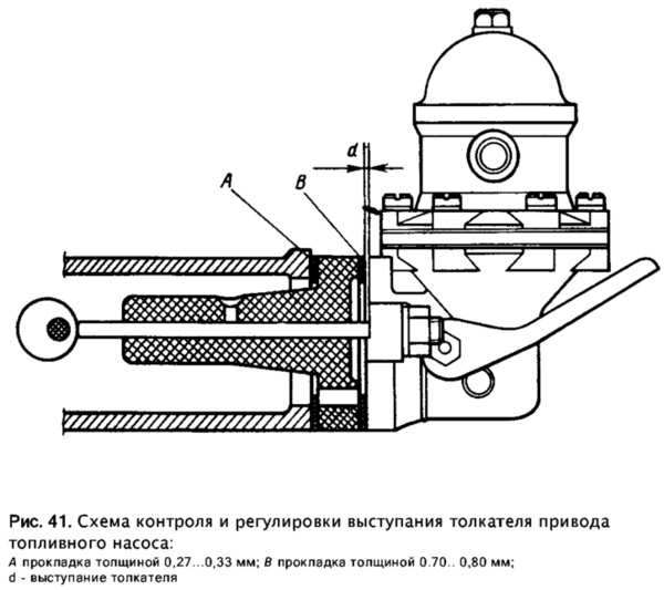
A heat-insulating spacer and adjusting gaskets are installed between the pump and the drive housing. For correct installation of the pump, two of the three gaskets listed below are used: gasket A — 0.27...0.33 mm thick; gasket B — thickness 0.7...0.8 mm; gasket C — 1.1...1.3 mm thick. The installation diagram is shown in Figure 41.


A heat-insulating spacer and adjusting gaskets are installed between the pump and the drive…


The pump is installed in the following order. Install the heat-insulating spacer, placing gasket A under it, and place gasket B on the plane in contact with the pump. Measure the distance d (the minimum amount by which the pushrod protrudes, determined by slowly turning the crankshaft). If the size d is within 0.80...1.30 mm, then the pump is attached to the engine; if d is less than 0.80 mm, gasket B is replaced by gasket A; if d is greater than 1.30 mm, then gasket B is replaced with gasket C. Measure the dimension d again and attach the pump to the engine.

There must always be a gasket A between the drive housing and the heat-insulating spacer.


This article is available at russian, bulgarian, belarusian, ukrainian, serbian, croatian, romanian, polish, slovak, hungarian
The text was reviewed by the specialist: Grigory Vologodtsev

Share with friends:

Previous articles
VAZ-2109: Supply system
Next articles

Fuel tank device
Power supply system device
Fuel lines and fine fuel filter
Air filter and thermostat device
Exhaust gas system
The structure and operation of the carburetor
Main metering systems of the carburetor

More articles from other manuals on VAZ cars:
➠ Fuel pump device VAZ-21213 (1994-2006)
➠ Cleaning the carburetor fuel filter and fuel pump mesh filter VAZ-1111 (1988-1996)
➠ Fuel pump — inspection, disassembly and installation VAZ-2101 (1970-1983)
➠ Disassembly and assembly of the fuel pump VAZ-2105 (1979-2010)
➠ Fuel pump filter — cleaning VAZ-2106 (1976-2006)
Link in different formats to this page


Visitor comments

No comments yet


How much will 39 + 33 ?


VAZ-21099 (1990-2004) 
  • General information
  • Specifications
  • User manual
  • Maintenance
  • Car care
  • Troubleshooting
  • Power unit
  • Engine repair
  • Cooling and lubrication system
  • Power and exhaust system
  • Transmission
  • Car gearbox
  • Clutch and drive shafts
  • Chassis
  • Car suspension
  • Steering
  • Brake system
  • Body
  • Exterior
  • Interior
  • Doors and locks
  • Electrical equipment
  • Equipment and devices
  • Lighting and signaling
  • Engine electrics
  • Ignition system


VAZ-2109 (1984-1997) 
  • General information
  • Vehicle operation
  • Vehicle device
  • Power unit
  • Engine repair
  • Cooling and lubrication system
  • Supply system
  • Transmission
  • Clutch
  • Gearbox and drive
  • Chassis
  • Car suspension
  • Steering
  • Brake system
  • Body
  • Body elements
  • Electrical equipment
  • Engine electrics
  • Equipment and devices


VAZ-2108 (1984-2003) 
  • General information
  • Introduction to guide
  • Power unit
  • Engine repair
  • Cooling and lubrication system
  • Power and exhaust system
  • Transmission
  • Clutch and drive shafts
  • Car gearbox
  • Chassis
  • Front suspension
  • Rear suspension
  • Steering
  • Brake system
  • Body
  • Exterior
  • Interior
  • Doors and glass
  • Electrical equipment
  • Equipment and devices
  • Engine electrics
  • Ignition system


VAZbook.ru © 2017 · Mobile version · Contact with administration · Sitemap: EN BG BY UA RS HR RO PL SK HU · Site search · News and articles VAZ-1111 · VAZ-11113 · VAZ-2101 · VAZ-21011 · VAZ-2104 · VAZ-2105 · VAZ-21051 · VAZ-2106 · VAZ-21061 · VAZ-2107 · VAZ-21099 · VAZ-2109 · VAZ-2108 · VAZ-2110 · VAZ-2112 · VAZ-2114 · VAZ-2115 · VAZ-2121 · VAZ-21213 · VAZ-21214 ·
The site stores technical data using cookies to improve the service.