
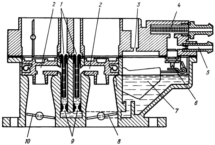
Pic. 46. Scheme of the main dosing systems:
1 - main air jets with emulsion tubes; 2 - sprayers of the first and second chambers; 3 - balancing hole; 4 - fuel filter; 5 - branch pipe with a jet for draining part of the fuel into the fuel tank; 6 - needle valve; 7 - float; 8 - throttle valve of the second chamber; 9 - main fuel jets; 10 - throttle valve of the first chamber.
When you press the throttle pedal, the throttle valve 10 of the first chamber opens, the vacuum in the diffusers, atomizer and emulsion well of the first chamber increases. As soon as the first holes of the emulsion tube open, the vacuum in the emulsion well decreases, and then, as the holes open, the difference between the rarefaction of the diffuser and the well increases. The fuel is entrained by air coming from the holes in the emulsion tube through the main air jet and directed through the atomizer to the diffuser and mixing chamber. Dosing of fuel and air in the main dosing system will be provided automatically by the main air jet and emulsion tube. The advantage of the emulsion tube is that it supplies air within the system itself, which makes it easier to atomize the fuel in the mixing chamber and distribute the fuel in the air stream.
The throttle valve of the second chamber is mechanically connected to the throttle valve 10 of the first chamber in such a way that it begins to open when the damper 10 is already open to two thirds of the full opening angle. At the same time, the main dosing system of the second chamber also starts to work in the same way as described above.
The amount of mixture entering the engine is controlled by the opening of the throttle valves. The first mixing chamber mainly operates in throttling modes, which ensures the operation of the engine in a wide range.