
English Русский
Български
Беларускі
Український
Српски
Hrvatski
Română
Polski
Slovenský
Magyar
| Articles | Contacts | Sitemap |   
Repair and maintenance Lada Repair and maintenance Mazda Repair and maintenance Mitsubishi Repair and maintenance Toyota Repair and maintenance Land Rover Repair and maintenance Hyundai Repair and maintenance Nissan
VAZbook.ru


Main     1111   2101   2105   2106   2107   2109   2110   2115   2121  
VAZ-2108 (1984-2003) VAZ-2109 (1984-1997) VAZ-21099 (1990-2004)
  • Main
  • «Sputnik»
  • VAZ-21099
  • Power unit
  • Engine repair
  • Removal and installation the engine

Removal and installation the engine (VAZ-21099)

            0

Contents: Removal the engine ↓ Engine installation ↓
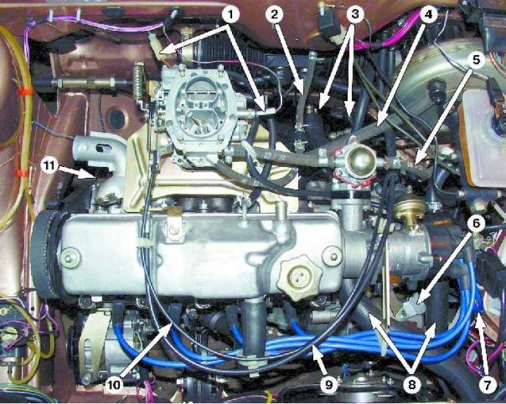
Engine (top view): 1 - pads with carburetor wires; 2 - fuel return drain hose; 3 - heater hoses; 4…

Engine (top view): 1 - pads with carburetor wires; 2 - fuel return drain hose; 3 - heater hoses; 4 - vacuum booster hose; 5 - fuel supply hose; 6 - Clutch cable tip; 7 - ignition coil wire; 8 - radiator hoses; 9 - throttle linkage; 10 - air damper rod; 11 - wire of the oil pressure warning lamp sensor
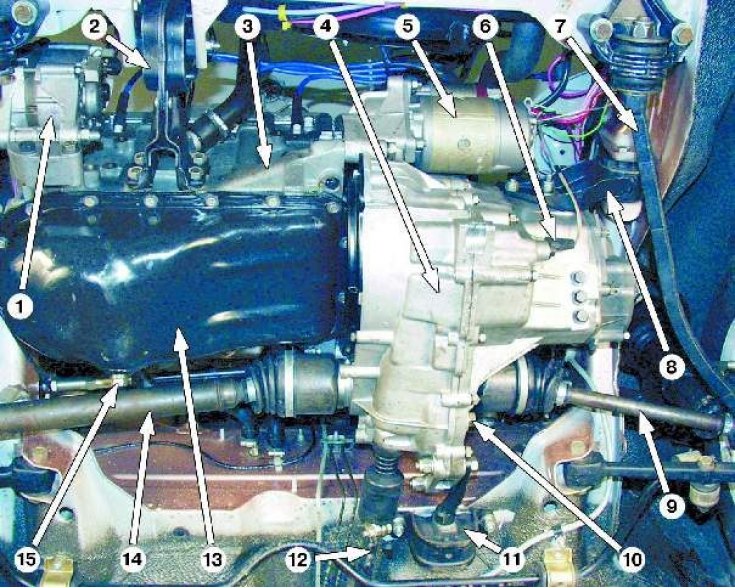

Engine (bottom view): 1 - generator; 2 - right front support; 3 - engine; 4 - gearbox; 5 - starter;…

Engine (bottom view): 1 - generator; 2 - right front support; 3 - engine; 4 - gearbox; 5 - starter; 6 - Reversing light switch; 7 - stretching; 8 - left front support; 9 - left front wheel drive; 10 - gearbox oil drain plug; 11 - rear support; 12 - gear shift drive rod; 13 - oil pan; 14 - right front wheel drive; 15 - Engine oil drain plug


Removal the engine


Before removing the engine, disconnect the wire from the "-" terminal of the battery.

Drain:
  • coolant;
  • oil from the engine crankcase (see subsection 11.12.);
  • gearbox oil (see subsection 11.12.).

Recommendations


Remove the engine assembly with the gearbox.

When removing the engine, lower it down from the engine compartment.

It is more convenient to remove the engine by placing the car on a lift.
It is more convenient to remove the engine by placing the car on a lift.


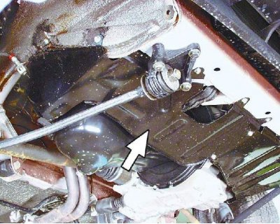
1.Loosen the mounting bolts and remove the crankcase guard.
1.Loosen the mounting bolts and remove the crankcase guard.


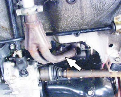
2. Remove the exhaust pipe (see subsection 11.6.1.).
2. Remove the exhaust pipe (see subsection 11.6.1.).


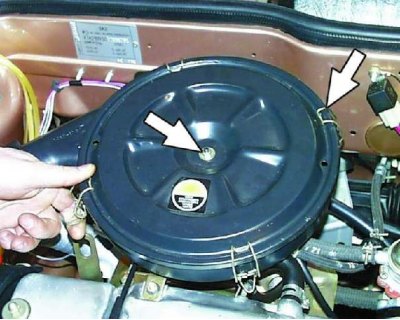
3. Remove the air filter (see subsection 11.2.).

3. Remove the air filter (see subsection 11.2.).


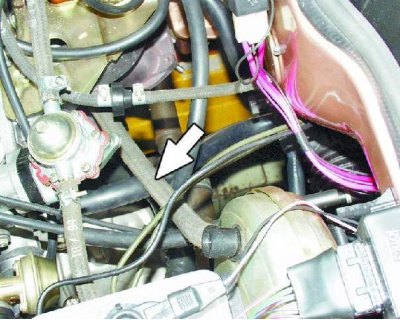
4. Loosen the clamp and disconnect the brake booster vacuum hose from the engine intake manifold.
4. Loosen the clamp and disconnect the brake booster vacuum hose from the engine intake manifold.


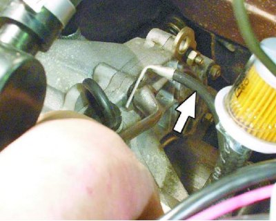
5. Loosen the bolt and disconnect the ground wire from the clutch housing.
5. Loosen the bolt and disconnect the ground wire from the clutch housing.


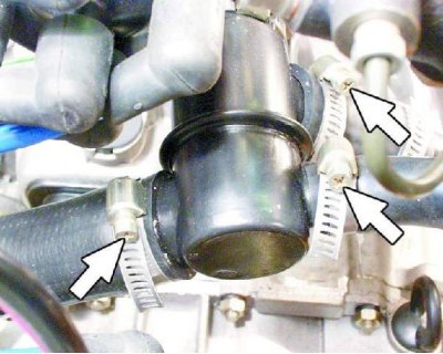
6. Loosen the clamps and disconnect the hoses from the thermostat.
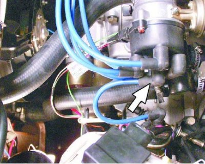
6. Loosen the clamps and disconnect the hoses from the thermostat.


7. Disconnect the high-voltage wire from the center terminal of the distributor cap.
7. Disconnect the high-voltage wire from the center terminal of the distributor cap.


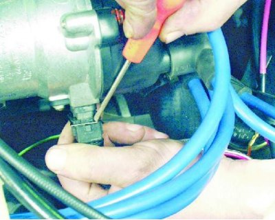
8. Use a screwdriver to press the spring clamp and disconnect the low-voltage wire connector from the distributor terminal.
8. Use a screwdriver to press the spring clamp and disconnect the low-voltage wire connector from…


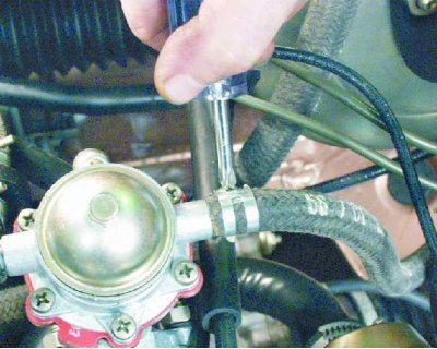
9. Loosen the clamp and disconnect the fuel supply hose from the fuel pump.
9. Loosen the clamp and disconnect the fuel supply hose from the fuel pump.


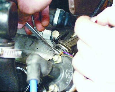
10. Loosen the nuts on the clutch release cable end.
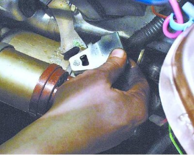
10. Loosen the nuts on the clutch release cable end.


11. Remove the cable end from the clutch release lever.
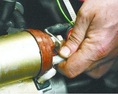
11. Remove the cable end from the clutch release lever.


12. Disconnect the connector with the wire from the starter solenoid relay terminal.
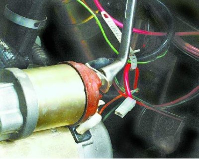
12. Disconnect the connector with the wire from the starter solenoid relay terminal.


13. Loosen the fastening nut and disconnect the wire from the contact bolt of the starter traction relay.
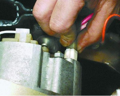
13. Loosen the fastening nut and disconnect the wire from the contact bolt of the starter traction…


14. Disconnect the connector with the wire from the generator terminal.
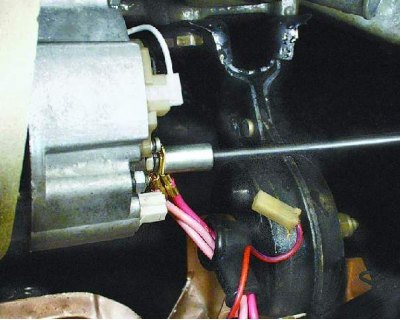
14. Disconnect the connector with the wire from the generator terminal.


15. Loosen the nut and disconnect the wires from the generator terminal.

15. Loosen the nut and disconnect the wires from the generator terminal.
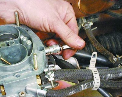

16. Disconnect the connector with the wire from the terminal of the carburetor shut-off solenoid valve.
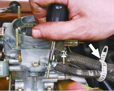
16. Disconnect the connector with the wire from the terminal of the carburetor shut-off solenoid…


17. Loosen the clamp and disconnect the fuel return hose from the carburetor. Remove the hose from the plastic clamp.
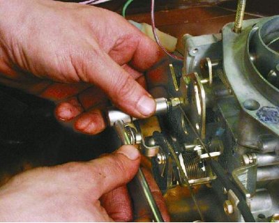
17. Loosen the clamp and disconnect the fuel return hose from the carburetor. Remove the hose from…


18. Loosen the bolt securing the choke rod to the choke control lever.
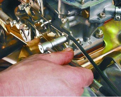
18. Loosen the bolt securing the choke rod to the choke control lever.


19. Loosen the bolt securing the air damper drive rod housing to the bracket and disconnect the cable.
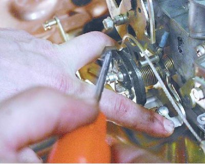
19. Loosen the bolt securing the air damper drive rod housing to the bracket and disconnect the…


20. Remove the accelerator cable spring clip from the throttle actuator sector.
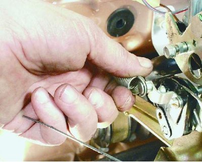
20. Remove the accelerator cable spring clip from the throttle actuator sector.


21. Remove the throttle actuator return spring.
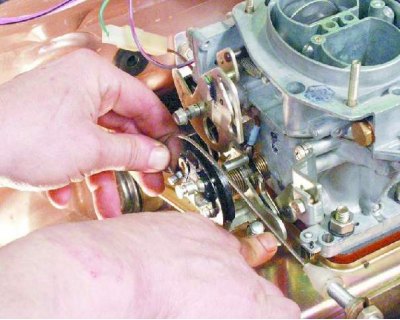
21. Remove the throttle actuator return spring.


22. Remove the accelerator drive cable from the throttle drive sector.
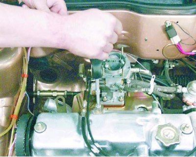
22. Remove the accelerator drive cable from the throttle drive sector.


23. Loosen the mounting nut and remove the accelerator cable bracket from the valve cover.
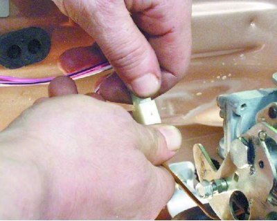
23. Loosen the mounting nut and remove the accelerator cable bracket from the valve cover.


24. Disconnect the connector with the wire from the forced idle speed economizer (FIS) limit switch.
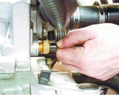
24. Disconnect the connector with the wire from the forced idle speed economizer (FIS) limit switch.


25. Disconnect the wire from the coolant temperature sensor.
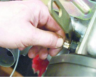
25. Disconnect the wire from the coolant temperature sensor.


26. Disconnect the wire from the oil pressure sensor.
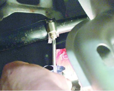
26. Disconnect the wire from the oil pressure sensor.


27. Loosen the clamp and disconnect the heater supply hose.
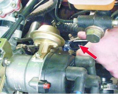
27. Loosen the clamp and disconnect the heater supply hose.


28. Loosen the clamp and disconnect the heater outlet hose.
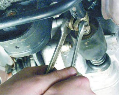
28. Loosen the clamp and disconnect the heater outlet hose.


29. Loosen the clamp and disconnect the gear shift rod from the joint end.
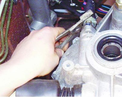
29. Loosen the clamp and disconnect the gear shift rod from the joint end.


30. Loosen the fastening nut and disconnect the cable from the speedometer drive.
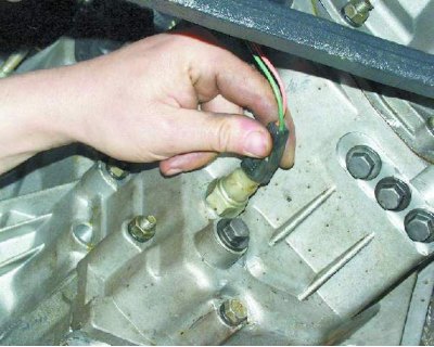
30. Loosen the fastening nut and disconnect the cable from the speedometer drive.


31. Disconnect the connector with the wire from the reverse light switch on the gearbox.
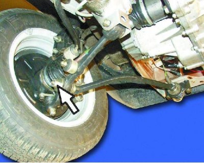
31. Disconnect the connector with the wire from the reverse light switch on the gearbox.


32. Loosen the nuts securing the left and right struts to the suspension arms.
32. Loosen the nuts securing the left and right struts to the suspension arms.


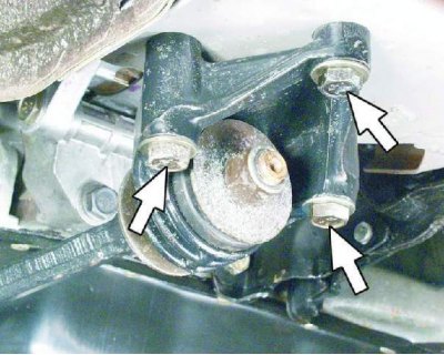
33. Unscrew the three bolts securing the strut bracket to the body and move the left and right struts to a position so that they do not interfere with the removal of the power unit.
33. Unscrew the three bolts securing the strut bracket to the body and move the left and right…


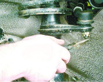
34. Remove the cotter pin from the nut securing the ball joint of the steering rod to the steering arm.
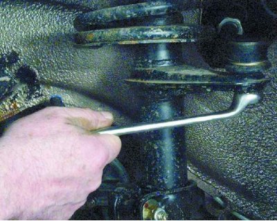
34. Remove the cotter pin from the nut securing the ball joint of the steering rod to the steering…


35. Loosen the nut securing the ball joint of the steering rod.
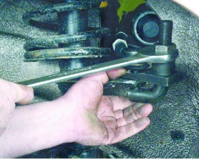
35. Loosen the nut securing the ball joint of the steering rod.


36. Press out the ball joint pin of the steering rod from the steering column pivot arm using a special puller.
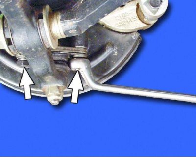
36. Press out the ball joint pin of the steering rod from the steering column pivot arm using a…


37. Remove the two bolts and disconnect the suspension arm ball joint from the steering knuckle.

37. Remove the two bolts and disconnect the suspension arm ball joint from the steering knuckle.
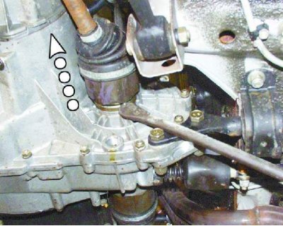

38. Using a pry bar, push the tail of one of the inner CV joints of the drive shafts out of the gearbox and move it to the side.
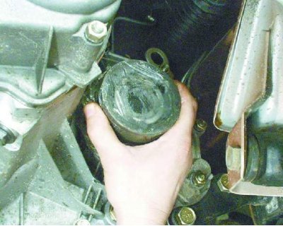
38. Using a pry bar, push the tail of one of the inner CV joints of the drive shafts out of the…


39. Insert a technological mandrel instead of a hinge (for example, an old inner CV joint), so that the axle gear does not turn. After this, disconnect the second CV joint in the same way as the first.
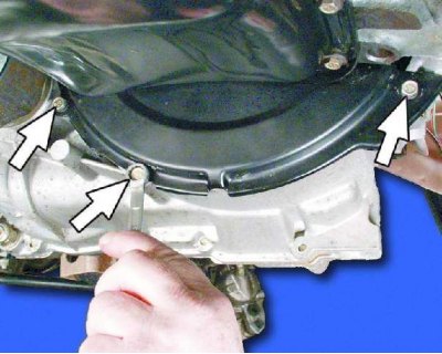
39. Insert a technological mandrel instead of a hinge (for example, an old inner CV joint), so that…


40. Unscrew the three mounting bolts and remove the clutch housing shield.

The operations specified in points 40 and 41 are performed to facilitate work on a removed engine with the gearbox.
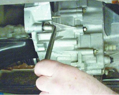
The operations specified in points 40 and 41 are performed to facilitate work on a removed engine…


41. Loosen the three bolts and nut securing the clutch housing to the cylinder block.
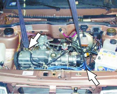
41. Loosen the three bolts and nut securing the clutch housing to the cylinder block.


42. Hook the engine to the eyes and tighten the hoist cables.
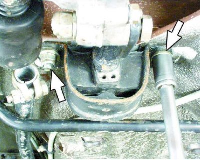
42. Hook the engine to the eyes and tighten the hoist cables.


43. Unscrew the two nuts securing the rear support of the power unit to the body.
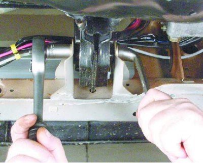
43. Unscrew the two nuts securing the rear support of the power unit to the body.


44. Loosen the nut, lift the engine slightly and remove the bolt from the right front support of the power unit.
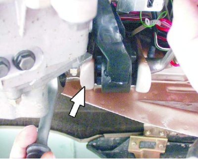
44. Loosen the nut, lift the engine slightly and remove the bolt from the right front support of…


45. Loosen the nut and remove the bolt from the left front support of the power unit.

46. Lower the engine onto stands, lift the car and remove the engine from underneath.

Before lowering the engine, check that all wires and hoses are disconnected from the engine.

Engine installation


Fill in:
  • coolant;
  • oil in the engine crankcase;
  • oil into the gearbox.

1. Tightening torques for threaded connections see Appendix 3. Finally tighten the threaded fasteners of the powertrain mounts and front suspension components after the vehicle is placed on the floor (before tightening, rock the front of the car two or three times).
1. Tightening torques for threaded connections see Appendix 3. Finally tighten the threaded…


3. After installing the engine on the vehicle, adjust the air and throttle valve drives of the carburetor, the clutch drive, and the front wheel alignment angles.

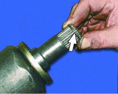
2. When connecting the front wheel drives to the transmission, replace the snap rings on the splined tails of the inner joints.

Do not install used snap rings on the splined tailpieces of the joints - this may lead to the front wheel drives becoming disconnected from the transmission while driving.

4. Start the engine and check for fuel, oil and coolant leaks. Check the oil pressure. Listen to the engine, it should run smoothly, without any extraneous noise or knocking. Check the operation of the control lamps in the instrument cluster.


This article is available at russian, bulgarian, belarusian, ukrainian, serbian, croatian, romanian, polish, slovak, hungarian
The text was reviewed by the specialist: Grigory Vologodtsev

Share with friends:

Previous articles
VAZ-21099: Engine repair
Next articles

Adjusting valve clearances
Complete disassembly of the engine
Cylinder block — inspection, defect detection and repair
Piston with connecting rod — disassembly, defect detection and assembly
Cylinder head — design description

More articles from other manuals on VAZ cars:
➠ The structure of a car engine VAZ-1111 (1988-1996)
➠ General structure of a car engine VAZ-2101 (1970-1983)
➠ The engine structure of VAZ-2104 and VAZ-2105 cars VAZ-2105 (1979-2010)
➠ The engine structure of VAZ-2106 and VAZ-2103 cars VAZ-2106 (1976-2006)
➠ Engine hood VAZ-2107 (1982-2012)
Link in different formats to this page


Visitor comments

No comments yet


How much will 31 + 34 ?


VAZ-21099 (1990-2004) 
  • General information
  • Specifications
  • User manual
  • Maintenance
  • Car care
  • Troubleshooting
  • Power unit
  • Engine repair
  • Cooling and lubrication system
  • Power and exhaust system
  • Transmission
  • Car gearbox
  • Clutch and drive shafts
  • Chassis
  • Car suspension
  • Steering
  • Brake system
  • Body
  • Exterior
  • Interior
  • Doors and locks
  • Electrical equipment
  • Equipment and devices
  • Lighting and signaling
  • Engine electrics
  • Ignition system


VAZ-2109 (1984-1997) 
  • General information
  • Vehicle operation
  • Vehicle device
  • Power unit
  • Engine repair
  • Cooling and lubrication system
  • Supply system
  • Transmission
  • Clutch
  • Gearbox and drive
  • Chassis
  • Car suspension
  • Steering
  • Brake system
  • Body
  • Body elements
  • Electrical equipment
  • Engine electrics
  • Equipment and devices


VAZ-2108 (1984-2003) 
  • General information
  • Introduction to guide
  • Power unit
  • Engine repair
  • Cooling and lubrication system
  • Power and exhaust system
  • Transmission
  • Clutch and drive shafts
  • Car gearbox
  • Chassis
  • Front suspension
  • Rear suspension
  • Steering
  • Brake system
  • Body
  • Exterior
  • Interior
  • Doors and glass
  • Electrical equipment
  • Equipment and devices
  • Engine electrics
  • Ignition system


VAZbook.ru © 2017 · Mobile version · Contact with administration · Sitemap: EN BG BY UA RS HR RO PL SK HU · Site search · News and articles VAZ-1111 · VAZ-11113 · VAZ-2101 · VAZ-21011 · VAZ-2104 · VAZ-2105 · VAZ-21051 · VAZ-2106 · VAZ-21061 · VAZ-2107 · VAZ-21099 · VAZ-2109 · VAZ-2108 · VAZ-2110 · VAZ-2112 · VAZ-2114 · VAZ-2115 · VAZ-2121 · VAZ-21213 · VAZ-21214 ·
The site stores technical data using cookies to improve the service.