




Attention. Do not touch the ECU terminals with your hands, as the engine management system is microprocessor-based and its electronic components may be damaged by electrostatic discharge.
Getting Started with Car Repairs (especially if the work involves dismantling elements of the engine control system), remove the terminal from the negative battery terminal.
Warning: Disconnecting the battery from the vehicle's network will erase the fault codes from the ECU memory. Therefore, before checking the engine management system using diagnostic equipment (for example, DST-2M) do not remove the terminals from the battery posts.
In many cases, to check the elements of the engine management system, it is necessary to have power supply voltage in the electrical circuit of the system. In this case, disconnect the wire connectors from the sensors
and actuators are allowed only after the ignition is turned off.
Caution: You can disconnect the wiring harness connector from the ECU only after removing the terminal from the negative battery terminal.
If it is necessary to connect the battery to the vehicle's electrical system during repairs, first make sure that the disconnected wires (connector terminals, wire ends) are not shorted to ground and the ignition is off. First connect the terminal to the positive terminal of the battery, then to the negative. Turn on the ignition only for the duration of the measurements.
Attention. The vehicle system uses electronic components with a supply voltage of 5 V. They are supplied with voltage from the vehicle's electrical network (voltage in which is more than 12 V) will result in failure of the engine management system.
To check the engine management system, use a multimeter, the internal resistance of the device in the voltmeter mode should be at least 10 MOhm. If necessary, to check the power supply circuits under 12 V, you can use a test lamp, but the lamp power should be less than 4 W. The instrument cluster test lamp A 12-1.2-1 with a power of 1.2 W or the cigarette lighter backlight lamp AMN 12-3-1 (3 W) will do.
Before starting the engine, make sure the terminals are securely connected to the battery posts.
Attention: To avoid damage to the electronic components of the ECU, do not disconnect the wire terminals from the battery terminals while the engine is running.
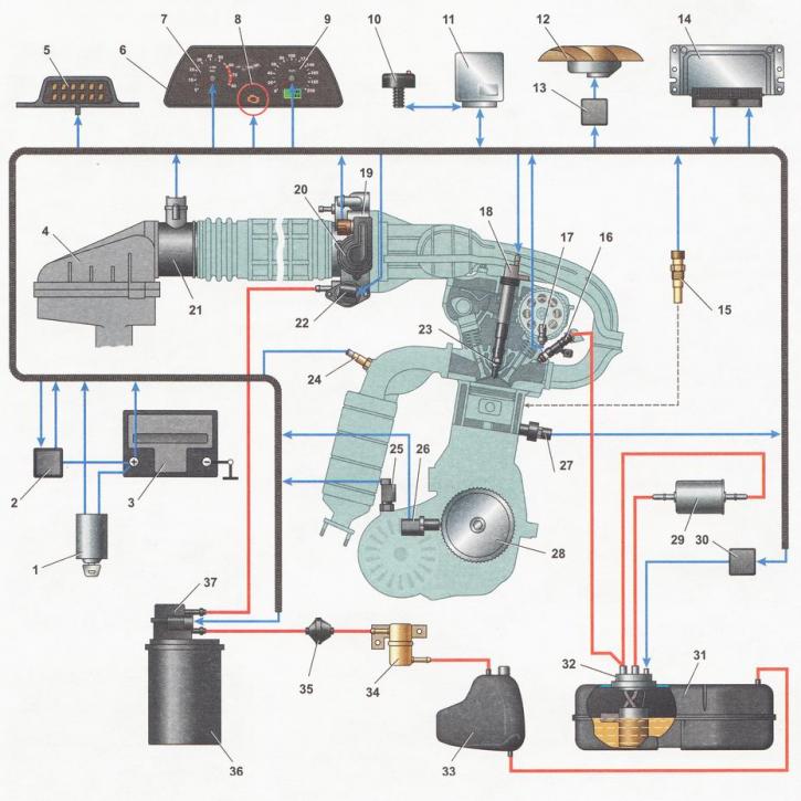
Injector engine control system diagram*: 1 - ignition switch; 2 - main relay; 3 - battery; 4 - air filter; 5 - diagnostic connector; 6 - instrument panel; 7 - tachometer; 8 - Engine management system malfunction indicator lamp; 9 - speedometer; 10 - immobilizer sensor with indicator; 11 - immobilizer control unit; 12 - Electric fan of the engine cooling system; 13 - Electric fan relay; 14 - Electronic control unit (ECU); 15 - coolant temperature sensor; 16 - injectors; 17 - camshaft position sensor (phase sensor); 18 - ignition coil*; 19 - throttle assembly; 20 - throttle position sensor (TPS); 21 - mass air flow sensor (MAF); 22 - idle speed control (ISC); 23 - spark plug; 24 - oxygen concentration sensor*; 25 - vehicle speed sensor; 26 - crankshaft position sensor (CPS); 27 - knock sensor (DS); 28 - crankshaft pulley; 29 - fuel filter; 30 - fuel pump relay; 31 - fuel tank; 32 - fuel module; 33 - separator; 34 - gravity valve; 35 - check valve; 36 - adsorber; 37 - purge valve of the adsorber
* The diagram is shown on the example of a car with an injection engine VAZ 21124 (l,6i). On a car with an engine VAZ 2112 (l,5i) instead of four coils an ignition module is installed; the oxygen concentration sensor is installed in the intake pipe.
The information is posted on the portal (www.vazbook.ru)