




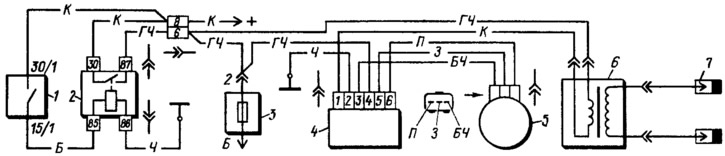
Figure 151. Ignition system diagram: 1 - ignition switch; 2 - ignition switch relay; 3 - fuse box; 4 - switch; 5 - spark timing sensor; 6 - ignition coil; 7 - spark plugs.
The spark discharge occurs simultaneously in both cylinders. In the cylinder where the compression stroke is ending, the spark discharge ignites the combustible mixture. In the other cylinder, where the exhaust stroke is ending, the discharge occurs idly.
Spark Timing Sensor type (model) 5620.3706, with vacuum and centrifugal ignition timing regulators and a built-in microelectronic control pulse sensor. The sensor produces pulses when a steel screen with slots passes through its groove.
Switch type 3620.3734, or 36.3734, or type HIM-52, or BAT 10.2 (hungarian production). It converts the control pulses of the sensor into current pulses in the primary winding of the ignition coil.
Ignition coil type 29.3705, with an open magnetic circuit, molded in plastic. Has two high-voltage terminals.
Spark plugs type FE65PR or FE65CPR.
Ignition switch type K.Z813 (hungarian production) or 2108-2704005-40 (domestic production) with an anti-theft locking device and with a blocking device against restarting the starter without first switching off the ignition. The switches are equipped with an additional ignition relay type 113.3747-10.