
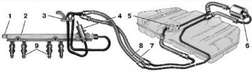
4.19. Fuel supply system with distributed injection: 1 - fitting for fuel pressure control; 2 - fuel rail; 3 - bracket; 4 - fuel pressure regulator; 5 - electric fuel pump; 6 - fuel filter; 7 - drain fuel line; 8 - fuel supply line; 9 - nozzles
Air filter 1 is mounted in the front of the engine compartment on rubber mounts. The filter element is paper, flat, with a large filtering surface area.
Throttle assembly controls the amount of air entering the intake pipe. The amount of air entering the engine is controlled by a throttle valve connected to the accelerator pedal drive. The throttle assembly includes sensor 4 (pic. 4.20) throttle position and idle speed control 5. In the flow part of the throttle assembly (in front of and behind the throttle) there are vacuum extraction holes necessary for the operation of the crankcase ventilation system and the adsorber of the gasoline vapor recovery system. If the latter system is not used, then the adsorber purge fitting is closed with a rubber plug 7.
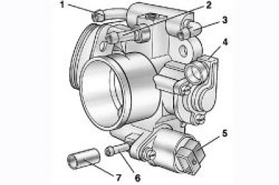
4.20. Throttle assembly: 1 - coolant supply pipe; 2 - branch pipe of the crankcase ventilation system at idle; 3 - branch pipe for draining the coolant; 4 - throttle position sensor; 5 - idle speed regulator; 6 - fitting for adsorber purge (used in the system of distributed injection with feedback); 7 - plug
idle speed controller 5 regulates the idle speed by controlling the amount of air supplied to bypass the closed throttle. It consists of a two-pole stepper motor and a cone valve connected to it. The valve extends or retracts according to the controller signals. When the regulator needle is fully extended (which corresponds to 0 steps), the valve completely blocks the air passage. When the needle is pushed in, an air flow is provided that is proportional to the number of steps the needle moves away from the seat.
Fuel supply system includes electric fuel pump 5 (see fig. 4.19), fuel filter 6, fuel lines and fuel rail 2 complete with injectors 9 and fuel pressure regulator 4.
Fuel pump - with electric drive, two-stage, rotary type, non-separable, installed in the fuel tank, which reduces the possibility of vapor locks, since the fuel is supplied under pressure, and not under vacuum. It provides fuel supply under pressure more than 284 kPa.
Fuel filter 6 is built into the supply line between the electric fuel pump and the fuel rail, installed under the floor of the body behind the fuel tank. The filter is non-separable, its body is steel with a paper filter element.
fuel rail 2 is a hollow bar with injectors and a fuel pressure regulator mounted on it. The ramp is fixed with two bolts on the intake pipe. From the left side (on the image) on the ramp there is a fitting 1 for controlling the fuel pressure, closed with a screw plug.
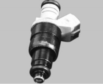
nozzles 9 (see fig. 4.19) attached to the ramp, from which fuel is supplied to them, and with their atomizers they enter the openings of the intake pipe. In the openings of the ramp and the inlet pipe, the nozzles are sealed with rubber sealing rings. The nozzle is a solenoid valve. When a voltage pulse arrives at it from the controller, the valve opens and fuel is injected through the atomizer with a finely sprayed jet under pressure into the intake pipe to the intake valve. Here, the fuel evaporates, in contact with heated parts, and enters the combustion chamber in a vapor state. After the electrical impulse is stopped, the spring-loaded injector valve shuts off the fuel supply.
Fuel pressure control 4 is mounted on the fuel rail and is designed to maintain a constant pressure difference between the air pressure in the intake pipe and the fuel pressure in the rail.

4.21. Fuel pressure regulator: 1 - housing; 2 - cover; 3 – a branch pipe for a vacuum hose; 4 - diaphragm; 5 - valve; A - fuel cavity; B - vacuum cavity
The regulator consists of a valve 5 (pic. 4.21) with diaphragm 4, pressed by a spring to the seat in the regulator body. With the engine running, the regulator maintains the pressure in the injector rail within 284–325 kPa. The regulator diaphragm is acted upon by fuel pressure on one side and fuel pressure on the other (underpressure) in the intake pipe. When the pressure in the intake pipe decreases (throttle valve closes) The regulator valve opens at a lower fuel pressure, allowing excess fuel to flow through the return line back to the tank. The fuel pressure in the rail drops. When the pressure in the intake pipe increases (when opening the throttle) the regulator valve opens already at a higher fuel pressure and the fuel pressure in the rail rises.
Arrangement of elements of the power supply subsystem of the distributed fuel injection system without feedback: 1 - air filter; 2 - air supply pipe; 3 - fuel pressure regulator; 4 - fuel rail; 5 - receiver; 6 - throttle assembly