




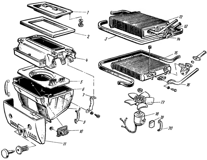
Figure 177. Heater: 1 - air intake cover; 2 - air intake cover gasket; 3 - radiator gasket; 4 — radiator casing; 5 — fan guide casing; 6 — fan casing; 7 — Fan casing mounting bracket; 8 - Air distribution cover; 9 — Fan casing mounting clamp; 10 - additional resistor; 11 — heater protective cover; 12 — radiator; 13 - supply pipe; 14 — edge; 15 - aluminum radiator (variant execution); 16 - outlet pipe; 17 — fan impeller; 18 - Electric motor; 19 — Electric motor cushion; 20 — spring bracket for mounting the electric motor.
Plastic radiator casing 4 is attached with four studs to the front panel reinforcement under the air intake box, which can be accessed under the instrument panel. The radiator casing with the air intake box is sealed with a rubber sealing gasket. Radiator 12 is installed in the radiator casing and sealed with a rubber gasket 3. The radiator consists of two rows of tubes, cooling plates and two tanks. The right radiator tank is divided by a partition into two cavities. A discharge pipe and tap 14 with an inlet pipe 13 are attached to the tank. The ends of the pipes exit into the engine compartment through the front panel and are connected with hoses to the cooling system. The outlet of the pipes into the engine compartment is sealed with a rubber seal.
The air that has passed through the heater radiator enters the fan casing 6 through the guide casing 5. The electric fan is secured in the center of the plastic guide casing with spring clamps 20. On the left wall of the fan casing 6, on the inside, there is an additional resistor 10 (resistor). Connecting it to or disconnecting it from the electric fan power supply circuit with a three-position switch ensures low or high speed of the fan impeller 17.
The heater is controlled by an electric fan switch, rotary deflectors and two handles 13 (figure 178) control of the valve and the air intake cover. The lower valve control handle is connected by a flexible rod 6 to the valve lever and regulates the amount of coolant entering the heater radiator. The upper handle is connected by a flexible rod / to the air intake cover lever, regulating the air flow into the heater. To make it easier to remember the position of the control handles, there are triangle-shaped symbols on the instrument panel on the left, the tops of which indicate that the air intake cover and valve are closed.
The information is posted on the portal: vazbook
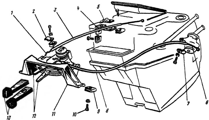
Figure 178. Heater control drive: 1 - flexible air intake cover control rod; 2, 5 and 7 - clamping brackets; 3 and 8 - flexible rod shells; 4 — bracket for fastening the thrust casing; 6 - Flexible crane control rod; 9 — spring nut for fastening the control lever bracket; 10 — mounting screw; 11 — control lever bracket; 12 — heater control levers; 13 — control lever handles.
Many parts and components of the heater are interchangeable with parts of cars VAZ-2101, VAZ-2105 and VAZ-2106. The following are interchangeable with the VAZ-2101 parts: radiator casing with air intake cover, fan casing with air distribution cover, tap with inlet and outlet pipes, electric fan assembly with fastening parts, control levers with bracket assembly. The following are interchangeable with the VAZ-2105 parts: heater radiator assembly with pipes, resistor; with VAZ-2106 parts, deflectors assembled with pipes are interchangeable.
It is prohibited to turn on the electric fan when the air intake cover is closed and the heater valve is open.