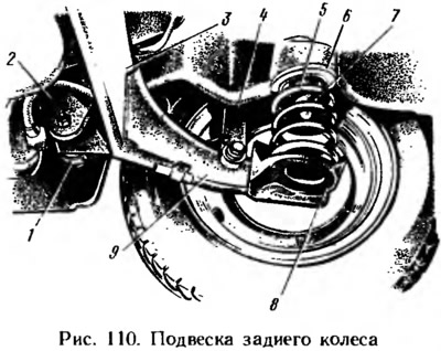
Suspension springs 5 are installed under the floor of the body, the lower part rests on the cups 8 of the levers, and the upper part - through rubber insulating gaskets 6 into the upper support, welded to the wheel arches and the floor of the body. Suspension compression stroke is limited by buffer 7.
Shock absorber 4 is installed in front of the spring, in the upper part it has a pin mount through rubber cushions with a bracket welded to the wheel arch. Details of the shock absorber are shown in fig. 112.
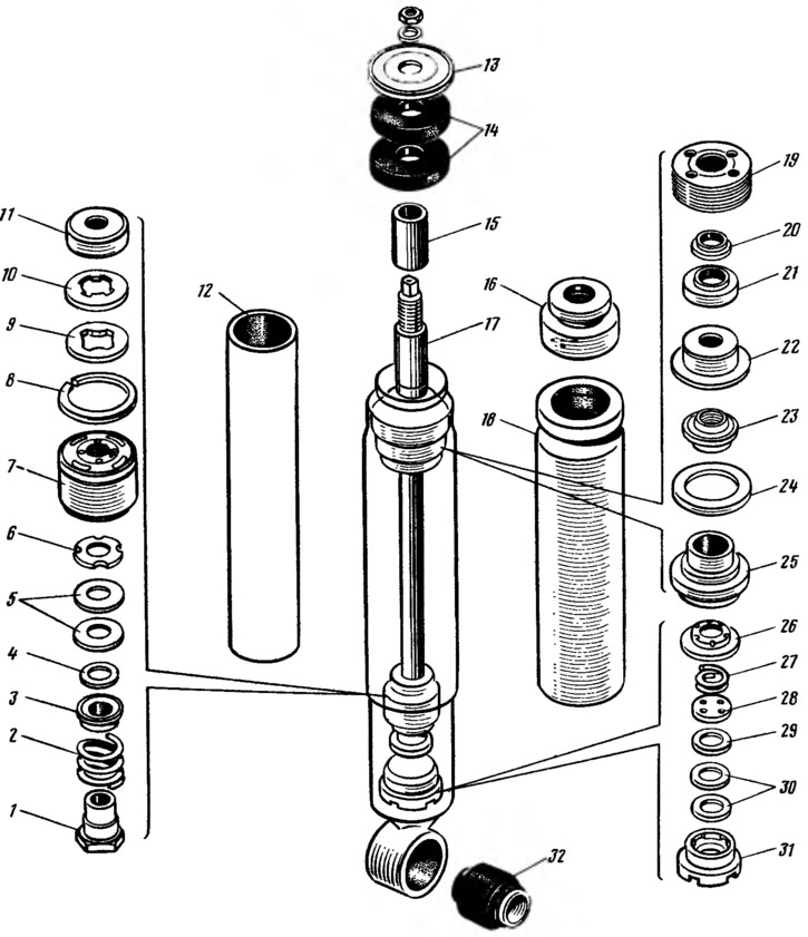
Pic. 112. Rear suspension shock absorber parts: 1 - recoil valve nut; 2 - recoil valve spring; 3 - recoil valve plate; 4 - washer of the recoil valve nut; 5 - recoil valve discs; 6 - throttle disc of the recoil valve; 7 - piston; 8 - piston ring; 9 - bypass valve plate; 10 - bypass valve spring; 11 - restrictive plate; 12 - cylinder; 13 - pillow washer; 14 - shock absorber cushions; 15 - spacer sleeve; 16 - cover of the protective casing; 17 - stock; 18 - protective cover; 19 - reservoir nut; 20 - protective ring of the rod; 21 - protective ring gasket; 22 - gland clip; 23 - stuffing box; 24 - sealing ring of the reservoir; 25 - rod guide sleeve; 26 - clip of the compression valve; 27 - compression valve spring; 28 - compression valve plate; 29 - throttle disc compression valve; 30 - compression valve disks; 31 - compression valve housing; 32 - rubber-metal shock absorber hinge.
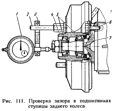
Hub 4 (pic. 111) the rear wheel is molded integrally with the brake drum. Tapered roller bearings 5 are installed in the hub, adjustable with a nut, which is fixed with a cotter pin.