




Install the support bushing 2 into the crankcase, making sure that its cutouts fit into the crankcase openings. Before inserting the support bushing into the crankcase, install the sealing rings 1 into its grooves so that the thin part of the rings is opposite the cut in the bushing. After installing the support bushing into the crankcase, cut the rings along the contour of the bushing, removing the cut parts.
Having generously lubricated the rack teeth with Fiol-1 grease, and its other surfaces with a thin layer of the same grease, install the rack in the crankcase, pushing it through the support sleeve 11 (figure 103) until it stops in a special device in order to maintain the size of (87±0.25) mm from the end of the rail to the axis of the rail stop.
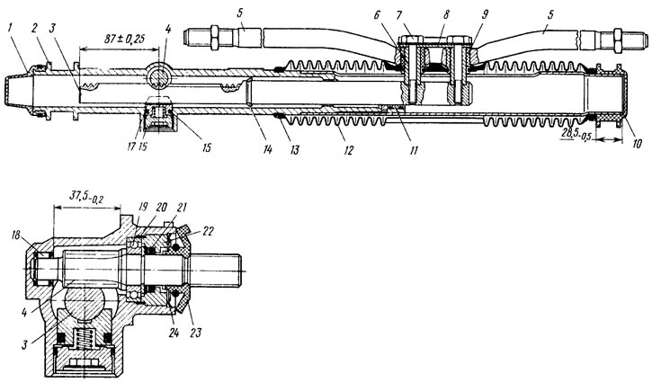
Figure 103. Steering mechanism: 1 - protective cap; 2 - steering gear housing; 3 - rail; 4 - drive gear; 5 - steering rod; 6 - spacer sleeve; 7 - steering rod mounting bolt; 8 - connecting plate; 9 - thrust sleeve; 10 - steering gear support; 11 - rack support sleeve; 12 - protective cover; 13 - clamp; 14 - rack thrust ring; 15 - rack stop sealing ring; 16 - nut; 17 - rack stop; 18 - roller bearing; 19 - ball bearing; 20 - retaining ring; 21 - nut sealing ring; 22 - gear bearing fastening nut; 23 - boot; 24 - washer
Apply Fiol-1 grease to the teeth of the drive gear and place it in the ball bearing until it appears on the upper end of the bearing. Then install the gear in the housing so that the chamfer on its shaft faces to the right (in the direction of the car) and press the bearing into the housing until it stops. The maximum bearing pressing force is 152.9 kgf. The total amount of grease for the rack, drive gear and bearing should be 20-30 g.
Using key 67.7812.9536, tighten the drive gear nut to a torque of (5±0.5) kgf·m, install retaining ring 11 (see figure 102) and fill the cavity above the nut with Uniol-1 grease.
The drive gear is set to the position of straight-line movement of the vehicle, which is determined by the size (87±0.25) mm in Figure 103. Then, using mandrel 67.7853.9586 (inner diameter 18 mm, outer diameter 24 mm), boot 23 is pressed onto the gear shaft so that marks A and B (see figure 101) on the boot and on the crankcase matched, and the boot fit tightly against the end of the crankcase.
Install the movable stop 15 (see figure 102) rails with sealing ring 16 until they stop in the rail (to a gap-free state). Install the pressure spring, locking ring 17 and tighten nut 18 with wrench 67.7812.9537 to a torque of 1.1-1.3 kgf·m, then loosen the nut by two divisions (24) to provide a gap of up to 0.12 mm between the nut and the rack stop, necessary to compensate for thermal expansion of parts and inaccuracies in their manufacture. The torque for unscrewing the nut must be at least 0.45 kgf·m.
After this, make sure that the gear rotation moment in the area of the entire stroke is within the range of 6-17 kgf-cm at a rotation speed of 30 rpm. If the gear rotation moment does not fit within the specified limits, identify and eliminate the causes of jamming of the parts, paying special attention to the rack stop, drive gear and rack. After this, punch the nut 18 of the stop at two opposite points. The position of the nut is marked with paint for control.
Install the protective cover 12 in place (see figure 103) so that its right end is at a distance of 28.5-0,5 mm from the end of the pipe and secure it with clamps. Then install support 10 so that it fits tightly to the boot. Secure the steering rods to the rack. Tighten the rod mounting bolts 7 with a torque of (7.8±0.8) kgf·m and lock them by bending the edges of the locking plate onto the face of the bolts.
After assembly, make sure that the protective cover does not have any bulges or pinches when the rack is moved at a gear rotation speed of 30 rpm, and that the gear rotation torque in the entire stroke is still within 6-17 kgf-cm at a rotation speed of 30 rpm. Otherwise, eliminate the causes of the detected defects. Check the gear rotation torque using dynamometer 02.7812.9501 with adapter sleeve 67.7812.9540. Make sure again that when the marks on the boot and on the steering gear housing match, the distance from the rack end to the drive gear axis is (87±0.25) mm.